Partial discharge testing measures small, localised electrical discharges inside high voltage insulation that do not yet bridge the full gap between conductor and earth. Those discharges are the earliest measurable sign that insulation is degrading. A partial discharge test finds the defect while the asset is still in service, so the owner can plan a repair instead of reacting to a failure. This guide covers partial discharge detection, how offline and online partial discharge testing differ, which IEC standards govern the measurement, and how Megavar engineers read the results on cables, switchgear and transformers.
Download the partial discharge testing guide (PDF)

What is partial discharge?
Partial discharge (PD) is an electrical discharge that only partially bridges the insulation between two conductors. It happens where the local electric field exceeds the breakdown strength of a small region of the insulation: a gas-filled void in cast resin or XLPE, a delamination at a cable termination, a sharp edge on a busbar, or contamination on an insulator surface. Each discharge is tiny, usually measured in picocoulombs or nanocoulombs of apparent charge (OMICRON, 2020), but it erodes the surrounding material a little further on every cycle of the supply voltage. Over months or years, the erosion grows into an electrical tree and the insulation fails.
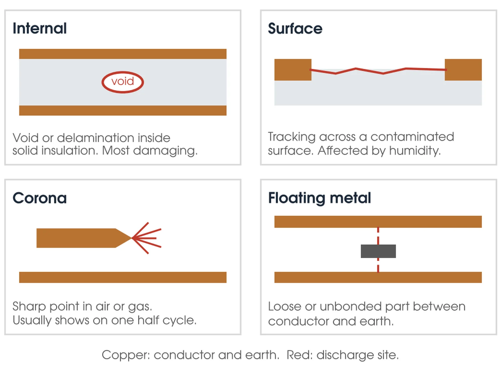
Most insulation systems used in medium and high voltage plant are not resistant to PD, so a discharging defect keeps degrading the insulation until it breaks down. The most common causes are defects introduced in manufacture and ageing in service, and internal discharges are generally the most dangerous type (OMICRON, 2020). On distribution networks, cable joints and terminations and metalclad switchgear are the usual places it is found (EA Technology, 2020).
How is partial discharge detected?
Partial discharge is detected by picking up the by-products of each discharge event: a fast current pulse in the conductor, an electromagnetic pulse in the radio frequency range, an acoustic emission, and in some cases ozone or light. Each by-product has its own sensor type, and the choice of sensor is what separates one PD test method from another.
| Detection method | What it senses | Typical sensor | Where it is used |
|---|---|---|---|
| Conventional electrical (IEC 60270) | Apparent charge pulse in picocoulombs, coupled through a coupling capacitor and measuring impedance | Coupling capacitor and quadripole into a PD measuring system such as the Omicron MPD 600 | Offline tests on cables, switchgear, transformers and rotating machines; factory acceptance and commissioning |
| High frequency current transformer (HFCT) | PD current pulses flowing in the cable screen earth connection | Split-core HFCT clamped around the earth strap | Online and offline cable testing, switchgear cable boxes |
| Transient earth voltage (TEV) | Voltage transients induced on the metal enclosure by internal PD | Capacitive TEV probe held against the panel, as in the EA Technology UltraTEV Plus2 | Online surveys of metalclad switchgear |
| Ultra high frequency (UHF) | Electromagnetic emission above 100 MHz, typically up to about 2 GHz (OMICRON, 2020) | UHF antenna or built-in UHF coupler | GIS, transformers, online switchgear |
| Acoustic and ultrasonic | Airborne or structure-borne sound from surface discharge or internal arcing | Ultrasonic microphone or contact acoustic sensor | Online surveys of open terminations, bushings and transformers; locating PD inside a tank |
In practice a competent PD test uses more than one of these at once. Megavar engineers run online switchgear surveys with TEV and ultrasonic sensors, and an HFCT on the cable earths where they are accessible, because internal PD is best detected by TEV and surface PD by ultrasonic (EA Technology, 2020). Surface discharge at a termination may be loud acoustically and invisible to TEV, while a void in a cast resin spout does the opposite.
Offline partial discharge testing
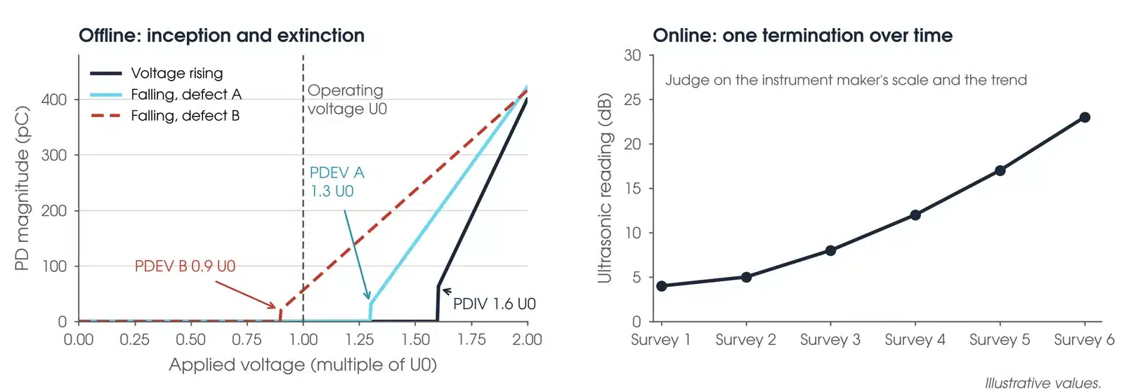
An offline PD test de-energises the asset, isolates it from the network and applies a controlled test voltage from a separate source while the PD measuring system records what the insulation does as the voltage rises. Because the engineer controls the voltage, the test can go above normal operating voltage, within the asset owner's limit and never above the rated power frequency withstand of the plant (AS/NZS IEC 60270:2026 cl 8), to find defects that only ignite under stress, and it can measure the two numbers that matter most for condition assessment: the partial discharge inception voltage (PDIV), where discharge starts as the voltage ramps up, and the extinction voltage (PDEV), where it stops as the voltage ramps down. A defect with a PDEV below operating voltage will discharge continuously in service and is the one to fix first.
The test source depends on the asset. For medium voltage cables the usual source is a very low frequency (VLF) set operating at 0.1 Hz, which keeps the reactive power manageable on long cable runs; Megavar combines its VLF sets with the Omicron MPD 600 so the VLF withstand test and the PD measurement happen in a single energisation. For switchgear and bushings the source is a power frequency or resonant test set. For a transformer the test voltage is induced through the LV winding at a frequency above rated so the core does not saturate (AS/NZS 60076.3:2017, Clause 11.1), with PD measured at the bushing taps. Megavar runs offline partial discharge testing on all three asset classes and holds resonant test sets rated to 300 kV and 500 kV for the larger jobs.
How to perform a partial discharge test?
The sequence for an offline partial discharge test on a cable or switchboard is the same regardless of the test source:

- Isolate, prove dead and earth the asset. Remove any surge arresters, VTs or other equipment that would load or clip the test voltage, and record what was disconnected. For a switchgear PD test to AS/NZS 62271.200 Annex B the VTs stay connected (B.4).
- Measure insulation resistance first. A cable or panel with a gross fault will not survive the PD test and will give no useful PD data. SA Power Networks limits this test to 5,000 V DC on 11 kV and 33 kV cables, because higher DC voltage on field-aged XLPE accelerates water tree growth (TS105, 2021).
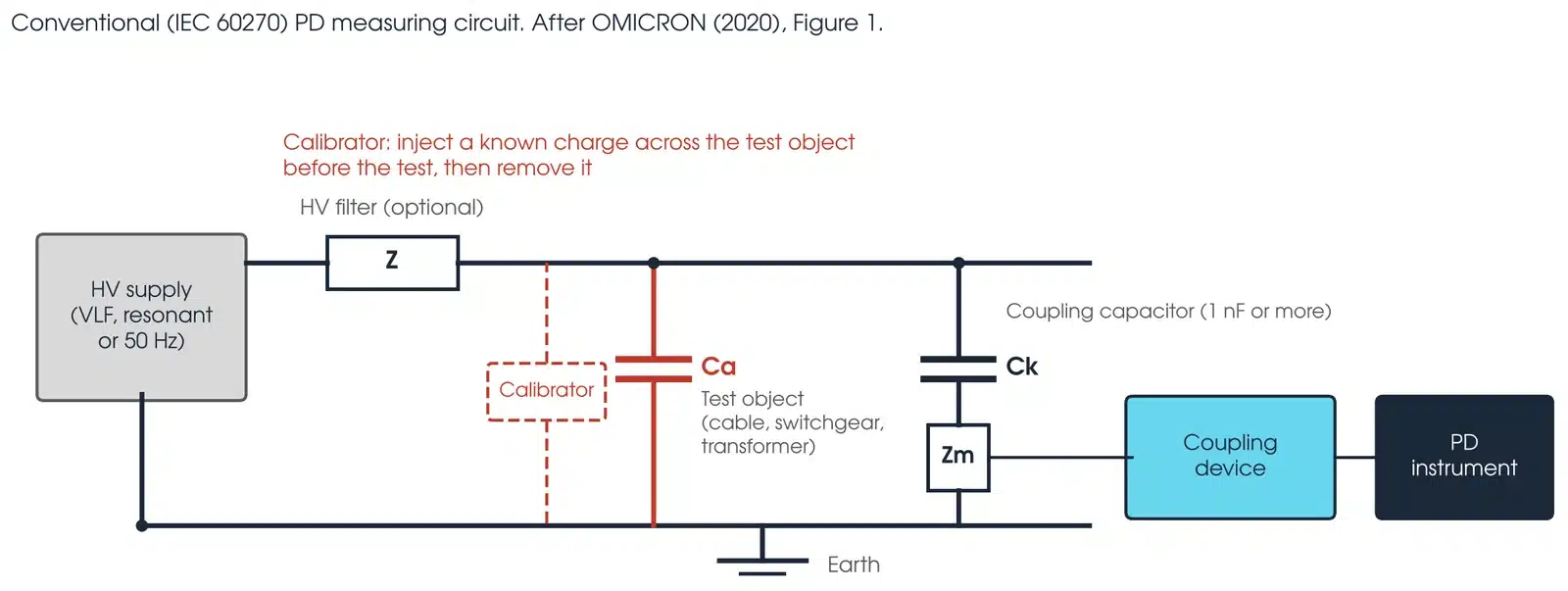
- Connect the PD measuring system. For IEC 60270 measurement this is a coupling capacitor in parallel with the test object and a measuring impedance; for a cable it may be an HFCT on the screen earth instead.
- Calibrate. Inject a known charge from a calibrator as close as possible to the test object terminals, between 50% and 200% of the specified PD magnitude (AS/NZS IEC 60270:2026, Clause 5), so the instrument reads apparent charge in picocoulombs rather than millivolts. Record the calibration factor and the background with the test source off, then check voltage-dependent interference separately with a PD-free reference at test voltage (Annex G.2). The smallest PD that can realistically be resolved is about twice the background (Clause 10).
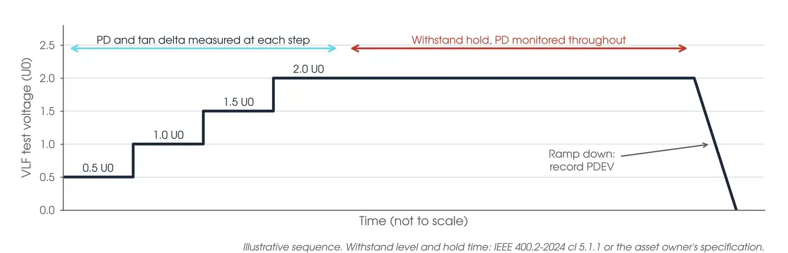
- Energise and ramp. Raise the voltage in steps to the test level set by the standard or the test plan, never above the asset owner's limit for that plant, holding at each step long enough to record the phase-resolved PD pattern. On a medium voltage cable, PD readings are commonly taken at 0.5, 1.0, 1.5 and 2.0 U0 before the withstand hold (BAUR, 2014), and IEEE 400.2-2024 takes its tan delta readings at 0.5 U0, U0 and 1.5 U0 (Clause 5.4.2).
- Record PDIV, the PD magnitude at U0 and at the hold voltage, and PDEV on the way down.
- On a cable, locate any PD source by time domain reflectometry on the PD pulses, which gives the distance to the defect along the cable.
- De-energise, discharge, re-earth and restore the disconnected plant. Report the phase-resolved patterns, the magnitudes against the acceptance limits, and the location of any defect.
Can I perform a partial discharge test online?
Yes. Online partial discharge testing measures PD while the asset is energised and carrying load, using non-intrusive sensors applied to the outside of the equipment. The test needs no outage, which is why utilities and industrial sites use it as a screening tool across whole switchrooms and cable populations. The trade-off is that the engineer cannot vary the voltage, so an online test gives PD activity at operating voltage only and cannot measure inception or extinction voltage.
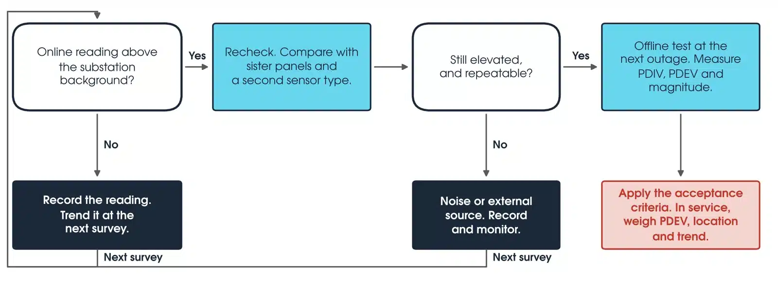
A typical online survey of metalclad switchgear takes TEV readings in decibels on the front and rear of every panel, ultrasonic readings at every door seal and vent, and HFCT readings on each cable earth strap where it is accessible. Panels that read well above the substation background are flagged, re-checked, and then either monitored or scheduled for an offline test on the next outage. Megavar uses the UltraTEV Plus2 for this work and hires it from the partial discharge testing rental range for customers who run their own surveys.
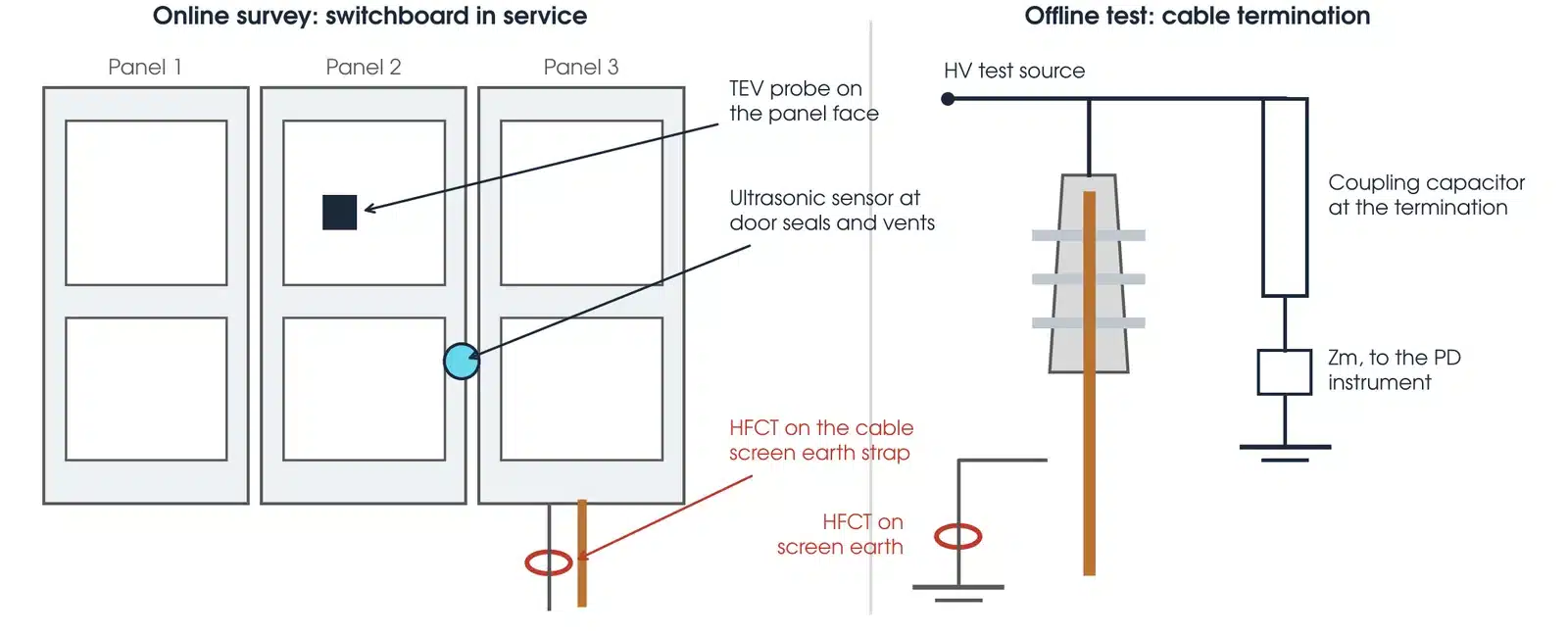
Online readings are judged on the instrument manufacturer's survey scale, in its own units and boundary values, together with the background, the phase-resolved pattern, the trend and the risk the asset carries. A reading at background is trended; an elevated, repeatable reading is rechecked with a second sensor type and compared with sister panels; a rising trend leads to an offline test that measures PDIV and PDEV and locates the defect.
| Offline PD test | Online PD test | |
|---|---|---|
| Outage needed | Yes | No |
| Test voltage | Controlled, can exceed operating voltage | Operating voltage only |
| Measures PDIV and PDEV | Yes | No |
| Calibrated in picocoulombs (IEC 60270) | Yes | No; dB, mV, counts or HFCT pC estimates, not IEC 60270 charge |
| Locates the defect | Yes, by TDR on cables and by sensor placement on switchgear | Approximately, by comparing sensor readings |
| Best use | Commissioning, acceptance, diagnosing a flagged asset | Screening a population, trending in service |
What is the IEC standard for partial discharge testing?
What is the IEC standard for partial discharge measurements?
IEC 60270 is the governing standard for conventional electrical PD measurement. Its current edition, IEC 60270:2025, is adopted identically in Australia as AS/NZS IEC 60270:2026, High-voltage test techniques: Charge-based measurement of partial discharges, which supersedes AS 60270:2001. It defines apparent charge, the measuring circuit, the calibration method and how the result is expressed in picocoulombs, so that a reading on one instrument can be compared with a reading on another. Every acceptance limit written into an equipment standard in picocoulombs assumes an IEC 60270 measurement.
The non-conventional methods (TEV, UHF, HFCT and acoustic) are covered by IEC TS 62478, High-voltage test techniques: Measurement of partial discharges by electromagnetic and acoustic methods. TEV, ultrasonic and UHF report in instrument-specific units, and some HFCT systems estimate charge in picocoulombs; none of these is IEC 60270 apparent charge, which is why an online survey result is reported as a trend, not against an IEC 60270 limit.
The acceptance limits themselves sit in the equipment standards, not in IEC 60270. The ones Megavar works to most often are listed below.
| Asset | Standard | What it specifies |
|---|---|---|
| Power transformers | AS/NZS 60076.3:2017 incorporating Amendment 1 (IEC 60076-3:2013 MOD), Clause 11.3 | Induced voltage test with PD measurement, measured and calibrated to IEC 60270 (Clause 11.3.4). The test passes if no PD level recorded during the one-hour period at 1.58 Ur/√3 exceeds 250 pC, the level rises by no more than 50 pC with no rising trend in the last 20 minutes, and the level at 1.2 Ur/√3 after the hour is 100 pC or less; the test is valid only with background PD of 50 pC or less (Clause 11.3.5). A miss leads to investigation between purchaser and manufacturer, not immediate rejection. |
| MV and HV cables, factory | IEC 60840:2020, Clause 9.2 (above 30 kV up to 150 kV); AS/NZS 1429.1:2006, Table 3.1 item 9(a), for MV cable; IEC 62067 above 150 kV | Under IEC 60840, each manufactured length is raised to 1.75 U0 for 10 s and reduced to 1.5 U0, and passes with no detectable discharge above the declared sensitivity of 10 pC or better for cable and 5 pC or better for accessories. Under AS/NZS 1429.1, the routine PD test on cables above 1.9/3.3 kV allows at most 20 pC at 200% U0 and 5 pC at 150% U0. |
| MV and HV cables, after installation | IEC 60840:2020, Clause 16.3; IEEE 400.2-2024; IEEE 400.3-2022, Table 4 | IEC 60840 allows a PD test under AC after installation by agreement, with the procedure, voltages and pass criteria agreed between customer and contractor; it sets no PD limit for the installed circuit. IEEE 400.2 covers VLF withstand and diagnostics and refers PD procedure to IEEE 400.3, the field guide for PD testing of shielded power cable systems (Clause 5.5). For acceptance testing below 69 kV, IEEE 400.3 Table 4 gives a prestress of 1.8 U0 and an accessory PDEV of at least 1.5 U0. |
| Metal-enclosed switchgear | AS/NZS 62271.200:2026 (IEC 62271-200:2021 Ed. 3.1 MOD), Clause 8.101 and Annex B | PD measurement is an optional routine test (Clause 8.101). Where it is done, the voltage is held at a pre-stress of 1.3 Ur for at least 10 s, then reduced to 1.1 Ur and the PD measured after 10 s; the permissible level is agreed between manufacturer and user (Annex B). A note to Annex B says limits for solid insulation seem to be about 20 pC at 1.1 Ur between phases, or 100 pC at 1.1 Ur phase to earth on non-solidly earthed neutral systems (B.5 Note 2). |
| Instrument transformers | AS 61869.2:2021 (current transformers) and AS 61869.3:2021 (voltage transformers), read with AS 61869.1:2024, Table 4 | PD measurement is a routine test on every unit (Clause 7.3.2). On an earthed neutral system, the limit for a CT or earthed VT is 10 pC (liquid or gas insulation) or 50 pC (solid insulation) at Um, and 5 pC or 20 pC at 1.2 Um/√3 (AS 61869.1:2024, Clause 5.4.3.1, Table 4). |
| Rotating machines | IEC 60034-27-1 (offline), IEC 60034-27-2 (online) | Measurement and interpretation of PD on stator windings. |
What is the difference between PD testing and VLF testing?
VLF testing is a withstand test: a 0.1 Hz voltage above the operating voltage is applied to the cable and the cable either survives or fails. IEEE 400.2-2024 bases its VLF withstand levels on roughly 1.7 U0 to 3 U0 and recommends 60 minutes on a new circuit and 30 minutes on an aged one, with 15 to 30 minutes able to be considered on medium voltage cable below 46 kV when the monitored PD or tan delta stays stable (Clause 5.1.1). The asset owner specification governs where it differs. It is a pass-or-fail proof test and gives no information about a cable that passes. Partial discharge testing is a diagnostic test: it measures the discharge activity in the insulation and reports where the defects are and how severe they are, without necessarily breaking anything. The two are complementary, and on a new or repaired cable Megavar normally runs them together, using the VLF set as the voltage source and the MPD 600 to measure PD during the withstand hold. A cable that passes the VLF withstand but shows PD at a joint at 1.5 U0 has a defect the withstand did not find, and only the PD measurement sees it.
What are the three big tests performed when testing a cable?
For a medium voltage power cable the three tests that matter are insulation resistance, the VLF withstand test, and the diagnostic pair of partial discharge and tan delta. Insulation resistance at up to 5 kV DC (the limit SA Power Networks sets for 11 kV and 33 kV cables) is a preliminary check that the cable is not grossly faulted; isolation, earthing, connections, equipment ratings and remote-end controls are confirmed separately before HV testing. The VLF withstand proves the cable can hold voltage above its operating level. PD and tan delta grade the insulation condition, PD by finding the localised defects and tan delta by measuring the overall dielectric loss, which rises as XLPE water-trees or paper insulation ages. A sheath integrity test on the outer jacket is normally added on buried cable. Megavar covers all of these on its HV cable testing service page.
What the results mean
A PD result is read in four parts: the magnitude, the inception and extinction voltages, the phase-resolved pattern, and the trend against earlier tests. No single number condemns an asset.
| Result | Interpretation |
|---|---|
| PD magnitude below the equipment standard limit at the test voltage, PDIV above operating voltage | Insulation is sound. Record as a baseline for future trending. |
| PD present above U0 but PDEV above operating voltage | A defect exists but is not discharging in service. On new plant, apply the acceptance criteria; in service, weigh location, pattern and trend before monitoring. |
| PDEV below operating voltage | The defect discharges continuously in service. Locate it and plan a repair or replacement. |
| Phase-resolved pattern symmetrical on both half cycles, in the rising part of each half cycle between the zero crossing and the peak | Internal void discharge, typical of a cavity in cast resin, XLPE or a joint. Few pulses per cycle, little affected by humidity, rarely audible. |
| Pattern concentrated on one half cycle only | Corona from a sharp point at one electrode. Less damaging to bulk insulation, but check the cause. |
| Broad, noisy pattern across the whole cycle with high repetition rate | Surface or tracking discharge, common at contaminated terminations. Many pulses per cycle, affected by humidity, often audible. Often fixed by cleaning and re-terminating. |
| Rising magnitude or falling PDIV between successive tests | The defect is growing. Bring the repair forward. |
The phase-resolved pattern is the part most often skipped in a report, and it is the part that tells the engineer what kind of defect is present. The report carries the phase-resolved pattern at each measurement point so the asset owner can see why a recommendation was made.
Where PD testing sits in a commissioning and maintenance programme
On new work, an offline PD test is part of the site acceptance of switchgear, cables and transformers, run after the installation tests and before energisation. On existing plant, an online survey at the interval the asset owner sets screens the population, and offline tests are reserved for assets the survey flags or that are due a major outage anyway. Megavar runs both halves of that programme for utilities, renewable generators and industrial sites, and hires the test equipment to customers who prefer to run their own surveys. The engineers who answer a rental enquiry are the same engineers who use the instruments on site, which is the practical difference between hiring a PD set from Megavar and hiring one from a general test equipment rental company.

Standards and references
AS/NZS IEC 60270:2026, High-voltage test techniques: Charge-based measurement of partial discharges (identical adoption of IEC 60270:2025).
IEC TS 62478, High-voltage test techniques: Measurement of partial discharges by electromagnetic and acoustic methods.
AS/NZS 60076.3:2017 incorporating Amendment 1 (2020), Power transformers, Part 3: Insulation levels, dielectric tests and external clearances in air.
IEC 60840:2020, Power cables with extruded insulation and their accessories for rated voltages above 30 kV (Um = 36 kV) up to 150 kV (Um = 170 kV). AS/NZS 1429.1:2006, Electric cables, Polymeric insulated, Part 1: For working voltages 1.9/3.3 (3.6) kV up to and including 19/33 (36) kV.
IEEE Std 400.2-2024, Guide for Field Testing of Shielded Power Cable Systems Using Very Low Frequency (VLF). IEEE Std 400.3-2022, Guide for Partial Discharge Field Diagnostic Testing of Shielded Power Cable Systems.
AS 61869.1:2024, AS 61869.2:2021 incorporating Amendment 1 (2022) and AS 61869.3:2021 incorporating Amendment 1 (2026), Instrument transformers. AS/NZS 62271.200:2026, High-voltage switchgear and controlgear, Part 200: AC metal-enclosed switchgear and controlgear for rated voltages above 1 kV and up to and including 52 kV.
OMICRON, A Guide for Partial Discharge Measurements on Medium and High Voltage Apparatus, Parts 1 and 2, 2020. OMICRON, Diagnostic Testing and Monitoring of MV Switchgear, 2026.
EA Technology, Introduction to Partial Discharge (IEEE Alberta), 2020. BAUR, VLF Sine 0.1 Hz Testing and Diagnostics, 2014. SA Power Networks, TS105 Testing Standard, 2021.
Download the partial discharge testing guide (PDF)
Frequently Asked Questions
How to perform a partial discharge test?
Isolate and earth the asset, measure insulation resistance, connect the PD measuring system and calibrate it with a known charge in picocoulombs, then energise from a VLF, power frequency or resonant test source and raise the voltage in steps. Record the inception voltage, the PD magnitude at operating voltage and at the test voltage, and the extinction voltage on the way down. On cables, locate any PD source by time domain reflectometry on the PD pulses.
How is partial discharge detected?
Partial discharge is detected from the by-products of each discharge: a fast current pulse measured through a coupling capacitor or an HFCT (the IEC 60270 method), a transient earth voltage on the enclosure measured with a TEV probe, a UHF electromagnetic emission, or an acoustic emission picked up with an ultrasonic sensor. Competent surveys combine several methods because each defect type is louder in one than another.
What is the IEC standard for partial discharge testing?
IEC 60270 is the standard for conventional electrical partial discharge measurement, adopted in Australia as AS/NZS IEC 60270:2026, and defines apparent charge in picocoulombs, the measuring circuit and calibration. IEC TS 62478 covers the electromagnetic and acoustic methods (UHF, HFCT, TEV, acoustic). The pass or fail limits are in the equipment standards: AS/NZS 60076.3 for transformers, for example, sets a 250 pC ceiling in the one-hour induced test, within its full set of validity and trend conditions (Clause 11.3.5), and IEC 60840 for cable above 30 kV up to 150 kV sets a factory test sensitivity of 10 pC.
Can I perform a partial discharge test online?
Yes. Online partial discharge testing uses TEV, ultrasonic, HFCT and UHF sensors on the outside of energised equipment and needs no outage. It is the normal way to screen a switchroom or cable population. It measures PD at operating voltage only, so it cannot give inception or extinction voltage; an asset that an online survey flags is then tested offline on the next outage.
What is the IEC standard for partial discharge measurements?
AS/NZS IEC 60270:2026, High-voltage test techniques: Charge-based measurement of partial discharges, the identical Australian adoption of IEC 60270:2025. It is the reference for any PD result expressed in picocoulombs. Non-conventional measurements in decibels or millivolts follow IEC TS 62478 and are not directly comparable with a picocoulomb limit.
What is the difference between PD testing and VLF testing?
VLF testing is a pass-or-fail withstand test at 0.1 Hz that proves a cable can hold a voltage above its operating level; IEEE 400.2-2024 recommends 60 minutes on a new circuit and 30 minutes on an aged one. Partial discharge testing is a diagnostic measurement that finds and locates insulation defects. They are usually run together on medium voltage cables, with PD measured during the VLF hold, because a cable can pass the withstand test and still carry a discharging defect the withstand does not find.
What are the three big tests performed when testing a cable?
Insulation resistance, a VLF withstand test, and the diagnostic pair of partial discharge and tan delta. Insulation resistance at up to 5 kV DC is a preliminary condition check (isolation, earthing and connections are confirmed separately), the VLF withstand proves it holds voltage, and PD and tan delta grade the insulation condition and locate defects. A sheath test is added on buried cable.
Which partial discharge test equipment does Megavar use and hire?
Megavar uses the Omicron MPD 600 and MCC 210 coupling capacitor for IEC 60270 measurement, VLF sets and resonant test sets to 300 kV and 500 kV as the voltage source, and the EA Technology UltraTEV Plus2 for online TEV and ultrasonic surveys. The same instruments are available on short and long term hire from Megavar's partial discharge testing rental range, with technical support from the engineers who use them.
What does a partial discharge test report from Megavar include?
Calibration record and background noise level, PD inception and extinction voltages, PD magnitude at operating and test voltage for each phase, the phase-resolved PD pattern at each measurement point, defect location on cables, the result against the applicable standard limit, and a plain recommendation: accept, monitor, or repair.
Need partial discharge testing on a cable, switchboard or transformer?
Megavar runs offline and online PD testing across Australia, and hires the same PD test equipment our engineers use. Call 1300 730 499 or email service@megavar.com.au.