
Case study
22kV Switchgear Replacement: Design and Commissioning
Talk to an engineer: 1300 730 499 or service@megavar.com.au
- Client
- Distribution network utility
- Principal Contractor
- Tier 1 network contractor
- Asset Owner
- Distribution network utility
- Location
- 110/22 kV zone substation
- Voltage
- 110 / 22 kV
- Asset Type
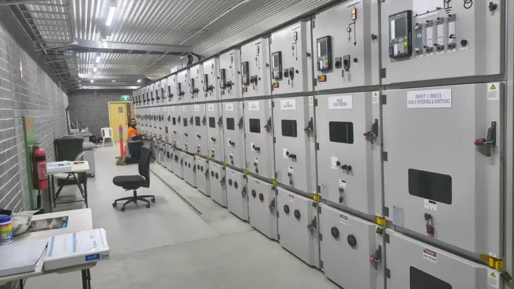
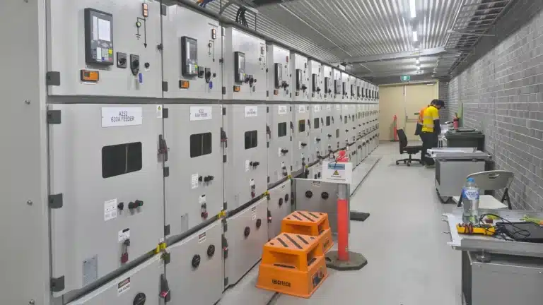
- 17 panel 22 kV arc fault contained switchboard
- Project Type
- Switchgear replacement: design, testing and commissioning
- Duration
- 14 months to energisation (December 2024 to February 2026)
- Megavar Scope
- Primary, civil and structural, building services, secondary and SCADA design; protection settings; FAT and SAT; HV withstand, PD and VLF testing; integration, testing and commissioning into the live substation
Overview
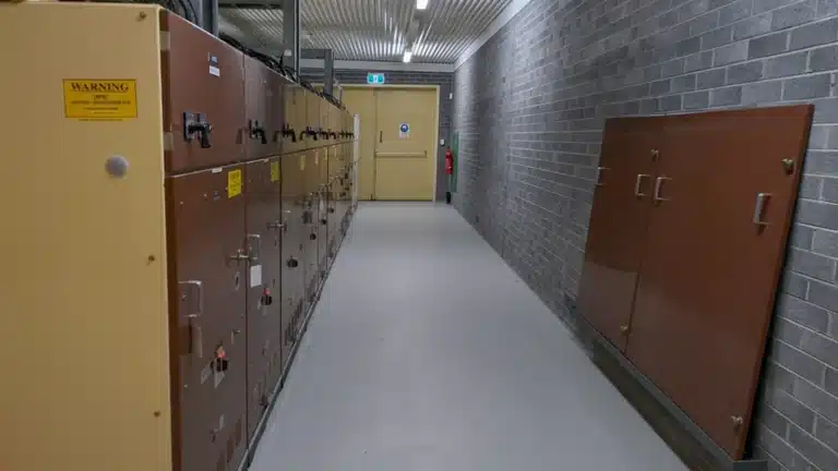
A 110/22 kV zone substation supplying a town and its surrounding distribution network needed its 22 kV switchboard replaced. Two 110/22 kV transformers feed two 22 kV buses, and the switchboard splits that supply across twelve outgoing feeders, one of which serves an embedded generator. The original metal clad switchgear had reached the end of its serviceable life and was not arc fault contained, so a 22kV switchgear replacement was needed with the substation kept in service.
The new board is a 17 panel arc fault contained switchboard with vacuum circuit breakers. Megavar was engaged by the head contractor to deliver the design and the testing and commissioning, with the switchgear, protection relays and network switches free issued by the asset owner and the installation carried out by others. Because the substation had to stay in service, the control building was extended by 4.5 m and the replacement was staged bus by bus, with one bus energised while the other was stripped out and rebuilt.
Megavar carried the design across primary, civil and structural, building services, secondary and SCADA disciplines, then tested and commissioned the new switchboard into the operating station. The work ran from December 2024 to energisation of the completed board in February 2026, with as-built design documentation issued in May 2026. It adds to Megavar’s utilities sector experience on network substations across Australia.
Scope of Work
- Design and testing and commissioning for a 22 kV switchboard replacement, delivered to the asset owner’s design and construct technical specification
- Primary, civil and structural, secondary and SCADA design issued through concept (30%), developed (80%), detailed (100%), IFC and as-built gates
- Control building extension design (4.5 m), including VESDA fire detection, DC emergency lighting, security and access control, and CCTV
- Staging design and secondary isolation planning for bus by bus removal of the existing switchgear with the adjacent bus energised
- Protection settings design, relay configuration and protection relay testing, with firmware aligned to the asset owner’s standard version and settings uploaded to its protection settings database
- Factory acceptance testing and site acceptance testing of the protection, control and SCADA systems
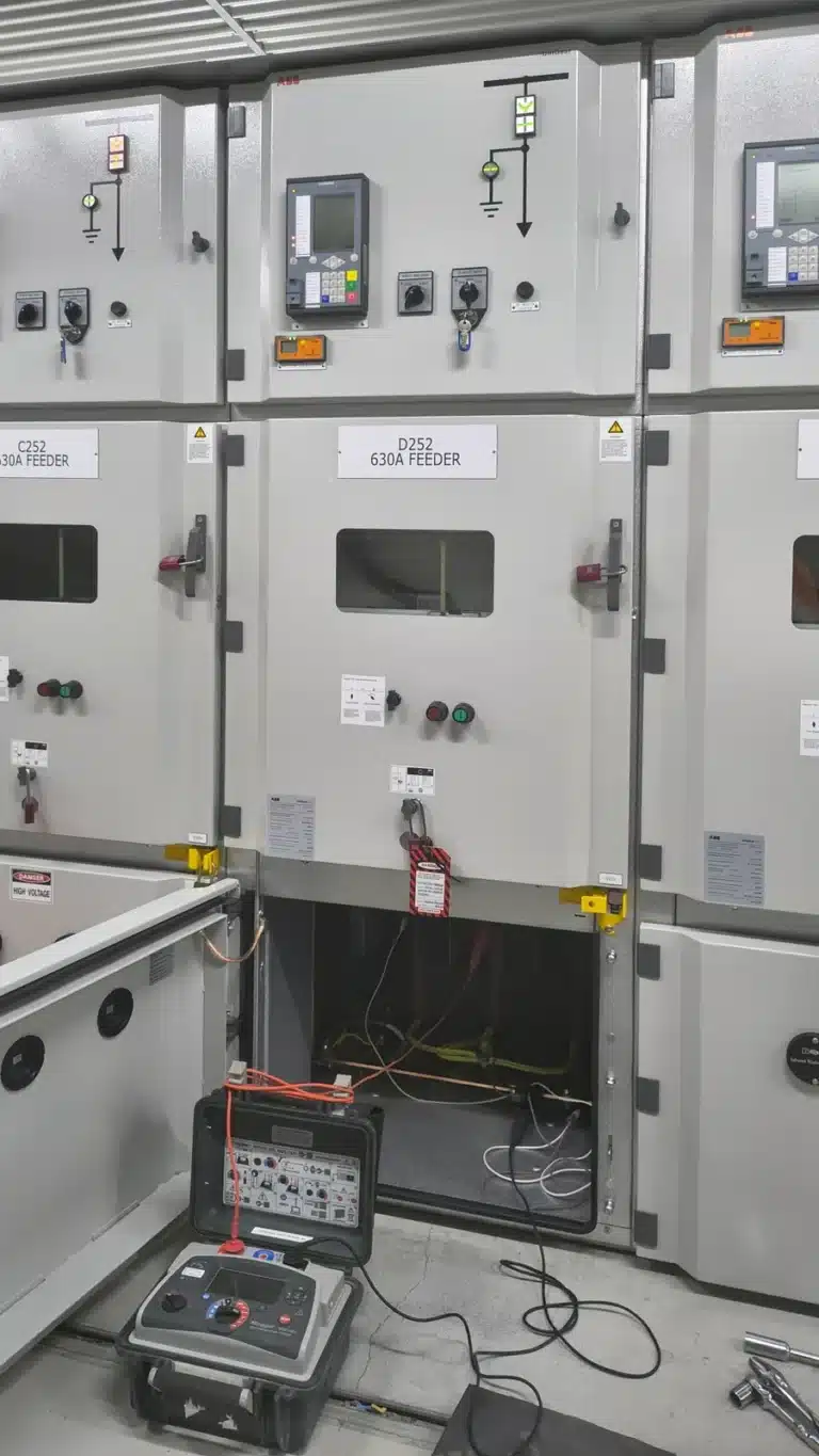
- HV withstand, partial discharge and 22 kV cable VLF testing, followed by staged energisation
- Integration with the in-service transformer T1 and T2 protection schemes, site gateway and revenue metering, with SCADA and RTU commissioning and end to end point testing back to the network control centre
- Building compliance documentation including occupancy permit, certificate of completion, bushfire assessment and geotechnical report
- NATA accuracy testing of revenue and check metering current and voltage transformers
Equipment Commissioned
- 22 kV switchgear: 17 x arc fault contained panels with vacuum circuit breakers: 2 x 2000 A incomers, 1 x 2000 A bus coupler, 2 x bus metering and VT cubicles, 12 x 630 A feeders (free issued by the asset owner)
- Protection relays: 17 x Siemens 7SJ82 (12 feeder, 2 incomer, 1 bus coupler, 2 busbar protection), firmware upgraded from v8.83 to v9.71 to match the asset owner’s standard version
- Substation LAN: 3 x Hirschmann RSP35 Ethernet switches and associated network
- 22 kV cables: Incomer and feeder cables: HV withstand, partial discharge and VLF testing
- Metering: Revenue and check metering CTs and VTs, NATA accuracy tested
- Protection schemes: Bus zone, bus coupler, incomer and feeder protection, interface and stability testing with the existing T1 and T2 transformer protection, live load blocking and auto reclose enable and disable for the embedded generator feeder
- SCADA: Station RTU and site gateway modification, IED mapping, HMI, end to end point testing to the network control centre
- Building services: VESDA fire detection, DC emergency lighting, security and access control for the building extension
Megavar Test Equipment Deployed
- Omicron: CMC 500, CMC 356, CPC 100, MPD 600
- HV Diagnostics: HVA60 VLF test set
- Phenix: 6CP50 50 kV AC hipot
- Megger: MIT515 5 kV insulation resistance tester, DLRO600 micro-ohmmeter
Omicron test sets like those used on this project are available for hire from Megavar, along with partial discharge test equipment for hire.
Team: Design: 2 senior design engineers, 2 design engineers, 2 drafters, with specialist SCADA design support. Testing and commissioning: core team of 2 to 3 engineers, increased to 6 during peak Bus A commissioning. Project management: 1 project manager.
Standards: Delivered to the asset owner’s design and construct technical specification and the standards it calls up for testing, commissioning and training, secondary equipment testing and recommissioning, SCADA systems, general substation requirements, high voltage systems, HV and LV cable systems, and lightning protection and earthing, together with the National Construction Code and state building permit requirements for the control building extension.
Challenges and Approach
Replacement in a live substation
Each 22 kV bus had to be stripped out and rebuilt while the adjacent bus stayed energised, and because the existing switchgear was not arc fault contained, arc flash segregation between the work area and the in-service bus was a permanent constraint on access and sequencing. Megavar developed a bus by bus staging and secondary isolation plan with the head contractor and the asset owner, revised through the programme, with progressive weekend works built into the sequence so the in-service bus was never left without protection. Arc flash segregation and access restrictions were designed into the staging rather than managed on the day.
The building extension on the critical path
The control building had to be extended by 4.5 m before the 22 kV B bus could be relocated and replaced, which put the civil and building works directly ahead of the electrical staging. Holding a single design authority across primary, civil, secondary and SCADA meant staging changes could be assessed and reissued quickly rather than negotiated between separate designers. Each design package was formally transmitted for client review at the concept, 80%, 100%, IFC and as-built gates.
Partial discharge on new switchgear
HV withstand and partial discharge testing on both buses identified PD sources that were not visible on inspection: contact springs requiring rectification between panels, a failed current transformer on one bus, and a further source on the other. Rather than replacing components on suspicion, the team split the bus and progressively isolated sections until each source was located. Replacement current transformers were PD bench tested before installation, retested after installation, and the affected phase retested again to confirm no other source remained. Every source was found and cleared before energisation.
Embedded generation on the network
The embedded generator on one feeder required live load blocking and auto reclose enable and disable logic on its feeder bay, live load blocking through voltage presence indicator contacts across the remaining feeders, and a back up feeder arrangement from the A bus. These schemes were designed, configured and tested as part of the protection scope.
Integration with an operating station
New protection and SCADA had to be integrated with the in-service T1 and T2 transformer protection, the existing site gateway and station RTU, revenue metering and a UFLS panel being decommissioned. An RFI and defect register was kept for the whole of testing: eight RFIs were raised, investigated, rectified with protection logic changes where required, retested across every affected feeder and formally closed, with the protection report and setting change notices reissued to match the as-commissioned state.
Holding the outage programme
Where testing windows came under pressure, additional testers were mobilised from another Megavar office and commissioning was moved into after hours and weekend work so the outage dates held. Relay firmware was upgraded to the asset owner’s standard version and as-commissioned setting files were uploaded to its protection settings database, so the asset handed over was already aligned with the client’s own standards and asset databases.
Outcomes
All seventeen 22 kV panels were tested, integrated and commissioned bus by bus with the substation in service, and both 22 kV buses were returned to full duty within the project programme. Every partial discharge source and protection defect identified during testing was located, rectified and retested before energisation.
- 17 x 22 kV panels tested and commissioned across two buses
- 17 x Siemens 7SJ82 protection relays configured, tested and commissioned, with as-commissioned settings uploaded to the asset owner’s settings database
- 12 x 22 kV distribution feeders tested and energised
- Multiple partial discharge sources located and cleared before energisation, including a failed current transformer, with its replacement bench tested and retested
- 8 RFIs raised, investigated, rectified and closed out during testing
- Control building extension designed, with occupancy permit and certificate of completion obtained
- Complete design delivered from 30% concept to as-built across primary, civil and structural, secondary, SCADA and CCTV
Reviewed by Megavar engineering team. Last reviewed October 2026. ISO 9001, ISO 14001, ISO 45001 accredited. Electrical contractors licences held in every Australian state.
Need High Voltage Testing or Equipment?
Tell us what you need and when, and we will come back with availability and pricing.
Get In Touch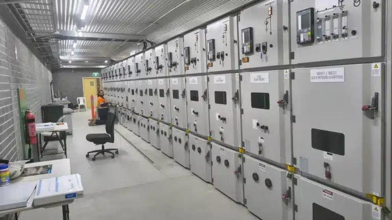
FAQ
Frequently Asked Questions
What is involved in replacing 22kV switchgear in a live substation?
Why was the 22kV switchgear on this project replaced?
What did partial discharge testing find on the new switchboard?
What design and commissioning work does a switchgear replacement need?
How long did the switchgear replacement take?
Does Megavar deliver substation switchgear projects across Australia?
Request a quote
Tell us about the job
An engineer replies by the end of the next business day (Monday to Friday, 8:30 am to 5:00 pm). Scope still forming? Send what you have. Hiring equipment? Use the equipment hire pages or email rentals@megavar.com.au.
Talk to us now
1300 730 499service@megavar.com.auHire: rentals@megavar.com.auMonday to Friday, 8:30 am to 5:00 pmTrusted by top enterprises for exceptional results


