An insulation resistance test applies a steady DC voltage across insulation and measures the small current that flows, giving a resistance in megohms, gigohms or teraohms. It is often called a Megger test, and the instrument a megohmmeter or insulation tester. Read as a one-minute spot value, or as timed ratios called the polarisation index (PI) and the dielectric absorption ratio (DAR), it shows whether the insulation on a cable, winding or bushing is dry, clean and sound. This guide sets out the test voltage to use, the timed readings, how to connect and discharge safely and how to judge a result.
Download the insulation resistance testing guide (PDF)

What is an insulation tester used for?
An insulation tester is used to find moisture, contamination and ageing in insulation before they turn into a fault. Every winding, cable and bushing relies on insulation to keep current off earth and off its neighbours; when a leakage path opens through or over that insulation, the insulation resistance falls long before the insulation fails.
It is also the gate before any higher voltage test. IEEE Std 43-2013 (6.2) recommends that a machine with low PI and IR1 readings is not subjected to further high voltage testing. What the test does not show is withstand strength: insulation resistance is not directly related to dielectric strength, and a DC test may not find internal voids (IEEE Std 43-2013, 11.3).
Is an insulation resistance test the same as a Megger test?
Yes. Megger is a brand of insulation tester that became the everyday name for the instrument and the test, so "Megger test", "megging" and "insulation resistance test" all mean the same measurement.
What does megging a wire mean?
Megging a wire means testing its insulation with an insulation resistance tester: applying a DC test voltage between the conductor and earth, or between conductors, and reading the resistance. A healthy result is a very high resistance, in megohms or more.
When should insulation resistance be tested?
At the factory, where it is part of the routine test record; at commissioning, to set a baseline at a recorded voltage and temperature; before any high voltage test; in routine maintenance at the asset owner's interval, so the result can be trended; and after an event such as a fault, flooding, a repair or long storage.

Where is insulation resistance testing used?
Almost every item of HV and LV plant has its insulation resistance tested. The common items are below, with what a low reading usually points to and the test voltage, with its basis.
| Item | What a low reading points to | Test voltage and basis |
|---|---|---|
| Motor and generator windings | Moisture, surface contamination, cracked or aged insulation | 500 V DC below 1000 V rating, up to 5000 to 10 000 V above 12 kV (IEEE Std 43-2013, Table 1) |
| Power transformer windings | Wet paper and oil, a grounded winding, a winding-to-winding short or carbon tracking | Typically 500 V to 5000 V DC, never above the rms applied test voltage (IEEE Std C57.152-2025, 7.2.13.3) |
| MV XLPE cables | Installation damage, water in joints or terminations | 5 kV DC core to screen, 1 kV DC screen to earth (SA Power Networks TS105) |
| Switchgear and busbars | Tracking, contaminated insulators, moisture in the enclosure | To the manufacturer's and asset owner's specification |
| CT and VT secondaries and wiring | Damaged wiring, moisture in terminal boxes | 1 kV DC (AS 61869.1:2024, 5.4.5.3); consult the relay maker above 500 V (IEEE Std C57.13.1-2017, Clause 10) |
| Transformer auxiliary wiring | Damaged or wet control wiring | 1 kV DC for 1 min on site (AS/NZS 60076.3:2017, Clause 9 note) |
What should my insulation resistance test be?
The test voltage comes from the plant. For rotating machines, IEEE Std 43-2013, Table 1, sets it by winding rating, from 500 V below 1000 V up to 5000 to 10 000 V above 12 kV. For transformers, the DC voltage to ground should not exceed the rms low-frequency applied test voltage (IEEE Std C57.12.90-2021, 10.11.3; IEEE Std C57.152-2025, 7.2.13.3). For 11 kV and 33 kV cables, SA Power Networks limits field tests to 5000 V DC and does not treat 5000 V DC as an HV DC test (TS105, 8.3).
The result to aim for depends on the item. For machine windings, IEEE Std 43-2013 (now Inactive-Reserved) sets a minimum PI of 1.5 for class 105 (A) and 2.0 for class 130 (B) and above (Table 3), disregarded where IR1 at 40 °C exceeds 5000 MΩ or PI does not apply to the winding design (12.2). The minimum IR1 at 40 °C for the whole winding is kV + 1 MΩ for most windings made before about 1970 and all field windings, 100 MΩ for most AC form-wound windings built after about 1970, and 5 MΩ for random-wound stators, form-wound coils below 1 kV and DC armatures (Table 4). For transformers, comparison with factory or previous results is more significant than the absolute megohms (IEEE Std C57.152-2025, 7.2.13.4). Asset owners set their own criteria: for example, SA Power Networks sets 1000 MΩ minimum at 5 kV for new 11 kV and 33 kV XLPE cable, core to screen (TS105, Table 1).
Our recommendation is to use the asset owner's specification where there is one, then the standard for the plant, and to use the same voltage every time. Insulation resistance may vary with applied voltage, so compare only at the same voltage (IEEE Std C57.152-2025, 7.2.13.3).
Why not test at a lower or higher voltage?
Some defects only show at higher stress, and on machines with stress grading IEEE Std 43-2013 (5.1) notes more reliable resistance and PI values at 5 kV or more. Going higher has its own risks: wet insulation can break down, and Megger advises a 100 V or 250 V tester early in a dry-out. On field-aged XLPE, SA Power Networks prohibits DC above 5000 V because it increases water tree growth, and AS/NZS 1429.1:2006, Appendix F, states that "the d.c. testing of the primary insulation is not recommended" for cables after installation.
How does an insulation resistance tester work?
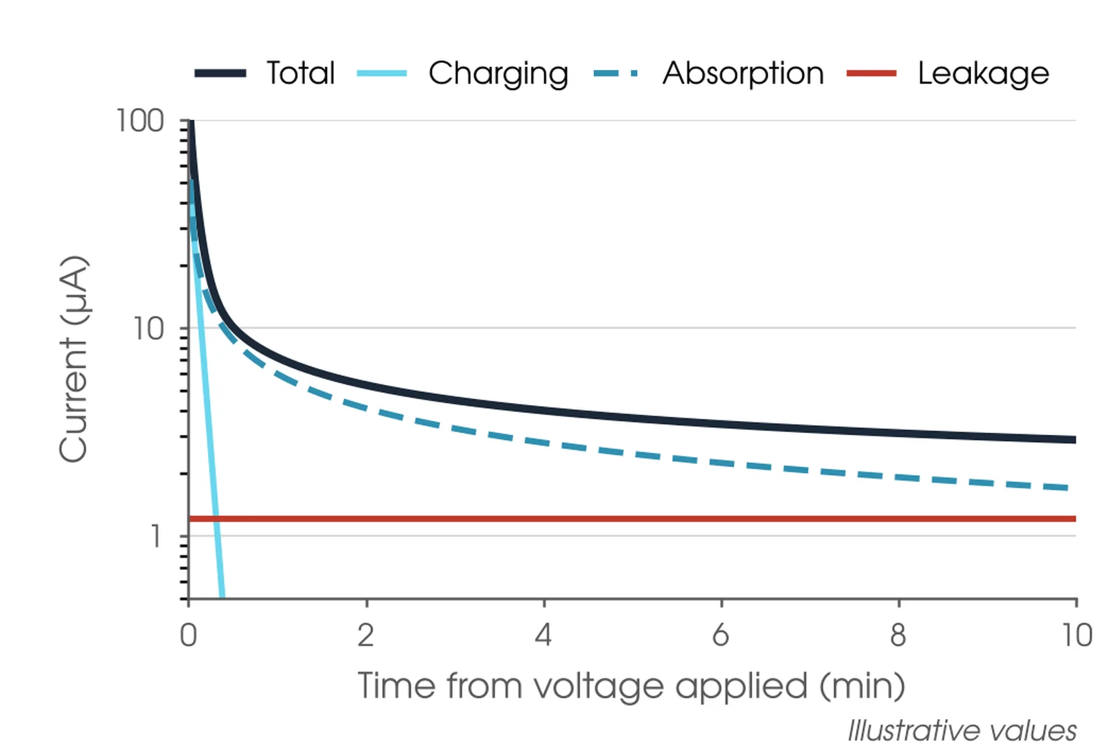
The tester applies a steady DC voltage and measures the current through and over the insulation; resistance is the voltage divided by the current. Three currents flow: a capacitive charging current that falls almost at once, an absorption current that decays over minutes, and a steady leakage current. Moisture and contamination raise the leakage and change how the absorption current decays, which is why the reading rises with time and why the time of each reading matters.
Moisture raises the leakage current faster than the absorption current, so wet insulation gives a flat reading and a low PI. Because temperature and humidity are the same for the 1 minute and 10 minute readings, the ratio cancels much of their effect (IEEE Std C57.152-2025, 7.2.13.5).
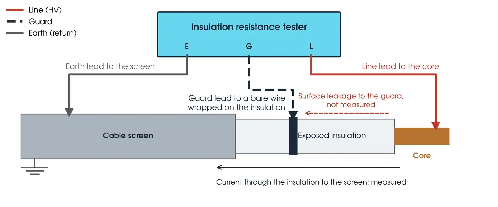
The tester has three terminals. Line is the high voltage lead, on the conductor or winding under test; IEEE Std 43-2013 (5.3) prefers negative polarity on the winding. Earth is the return, on the earthed tank, screen or frame and on everything not under test. Guard is a third lead that carries surface leakage around the measuring circuit, so the reading is the insulation itself and not the dirt on it. A guard is not an earth, and a guarded and an unguarded reading cannot be compared, so record whether it was used.
How do I set up an insulation resistance test safely?
The test puts up to 10 kV DC on de-energised plant, inside an access permit. Four steps come before any lead is connected:
- Confirm the permit covers the test, including removing the earth from the item under test. Earths are removed and replaced only by the person the asset owner authorises.
- Confirm the item is isolated, proved dead and earthed. Each exposed part is treated as energised until it is isolated and tested, and each HV part is earthed once de-energised (Safe Work Australia model Code of Practice: Managing Electrical Risks in the Workplace, 4.1).
- Disconnect what should not be tested: surge arresters, VTs, capacitors, relays and electronics. Record anything left connected (IEEE Std 43-2013, Clause 8).
- Barricade everything the test voltage reaches, including the far end of a cable (IEEE Std 43-2013, Clause 4).
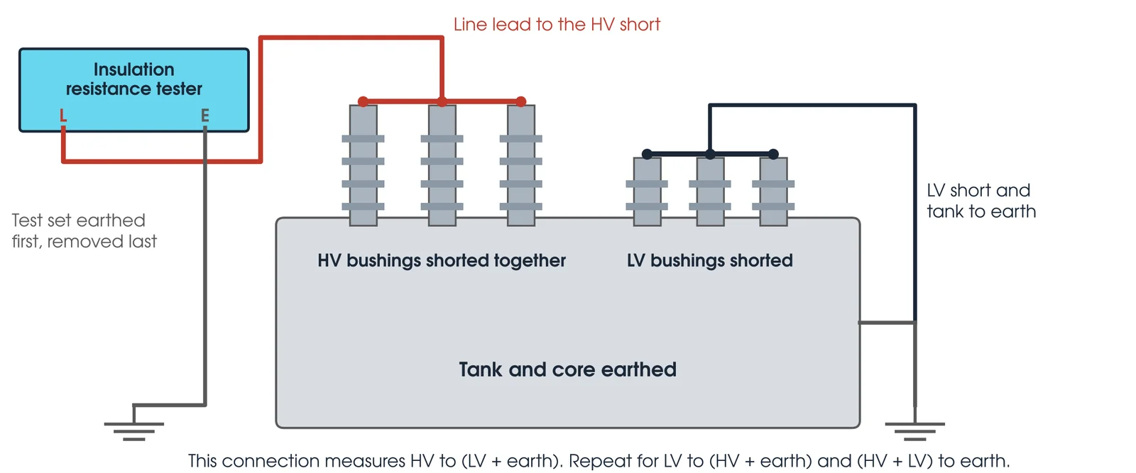
The main hazard is stored charge. A cable or winding charges like a capacitor and can hold a lethal charge after the test, so earth it for at least four times the voltage application time (IEEE Std 43-2013, Clause 4 and 6.5). The absorption current comes back out slowly, and a discharged item left unearthed can rebuild a dangerous voltage, so keep it shorted and earthed until it returns to service. Rather than remove a working earth from a line exposed to induction, disconnect the apparatus and leave the line earthed. Never test a transformer or CT under vacuum (IEEE Std C57.152-2025, 7.2.13; IEEE Std C57.13.1-2017, Clause 10), and consult the relay maker before exceeding 500 V on circuits with relays.
The test is for competent, authorised testing personnel working under the asset owner's safety rules. At Megavar that means assessed testers, with less experienced staff working under direct supervision. This guide describes general practice for competent HV testing personnel. It is not a work procedure. Work under the asset owner's safety rules, the access permit and a site-specific safe work method statement. Manufacturer and asset owner criteria take precedence over the general guidance here.
How do you test for insulation resistance?

- Isolate and prove dead. Under the permit, at the plant, with the permit issuer.
- Disconnect and short. Disconnect connected plant. Short each winding or core at its terminals and earth everything not under test.
- Discharge first. Begin only when there is no discernible return voltage, less than about 20 V, after the earth is removed (IEEE Std 43-2013, Clause 4).
- Connect and set voltage. Earth the test set first, then the earth lead, the line lead and the guard if used. Set the voltage used last time.
- Apply and time. Read at 30 s and 1 min for the spot value and DAR, and at 10 min for the PI. Stop at once if the current rises without settling (IEEE Std C57.152-2025, 7.2.13.3).
- Discharge and earth. Let the tester discharge the item, then apply an earth for at least four times the test time before touching a lead.
- Record and restore. Record the readings and conditions, remove the leads, then the test set earth last. Restore connections and earths per the permit.
Test above the dew point. A winding at or below it can carry a moisture film that lowers the reading (IEEE Std 43-2013, 6.2).
How to check Megger meter?
Check the instrument before relying on it. Confirm the calibration certificate is current, and inspect the leads and clips: they must be clean, dry and free of cracked insulation, and the lead set should not be used if any part is damaged (Megger, 2021). With the leads apart the tester should read over range, and with the leads joined it should read near zero. If you rely on the guard terminal, Megger suggests comparing guarded and unguarded readings on a calibration box with known leakage added.
What are the common insulation resistance testing mistakes?
| Mistake | What it does to the result |
|---|---|
| Different test voltage from last time | The two results cannot be compared |
| Connected plant left in the test | Every extra item lowers the reading and masks the item under test |
| Recording infinity | Over-range is not a number; record it as greater than the tester's maximum |
| No temperature recorded | The reading cannot be corrected or trended |
| Guard used inconsistently | A guarded reading is compared with an unguarded one |
| Leads touching each other or the ground | Above 100 GΩ this adds leakage to the reading (Megger, 2021) |
| Disconnecting too soon | Leads are removed before the item is discharged and earthed |
| Phases not under test left floating | They carry induced or stored charge |
How do I read an insulation resistance result?
An insulation resistance result is judged four ways: against the standard minimum for the plant, against the asset owner's criterion, against the factory or previous result at the same voltage and temperature, and by the shape of the time curve. A winding can pass its minimum and still need attention.
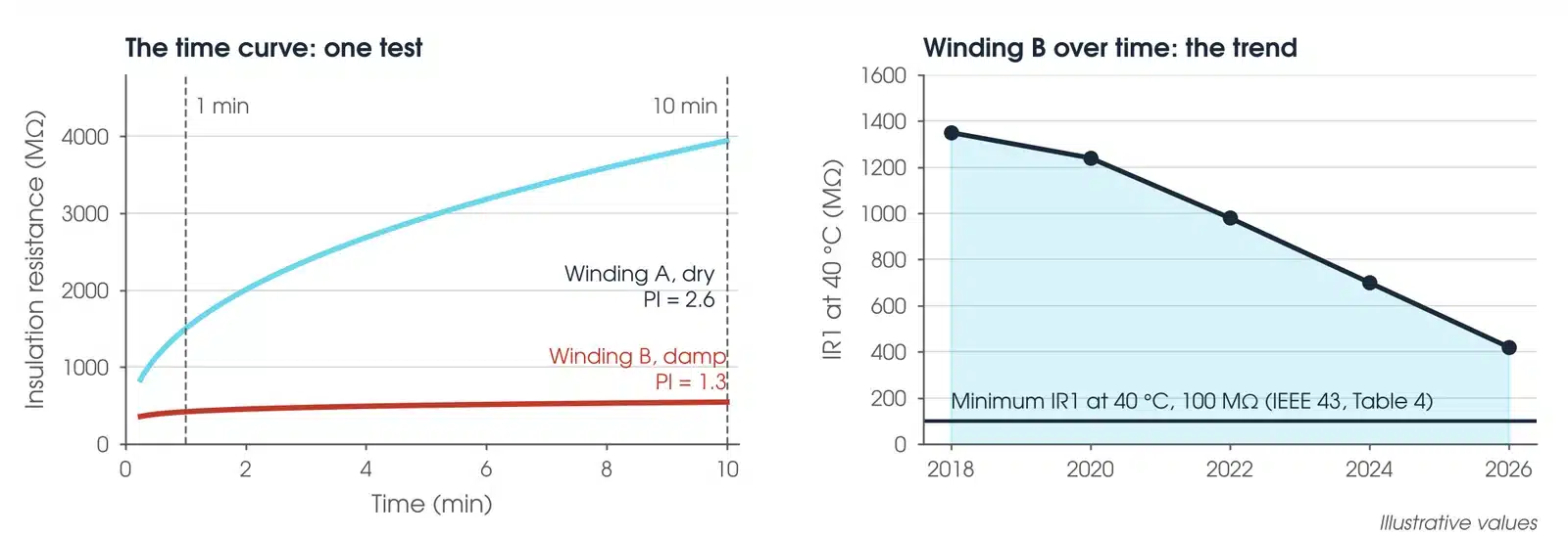
The DAR is a quicker ratio than the PI. AEMC gives a DAR below 1.25 as inadequate and above 1.6 as excellent, but IEEE Std 43-2013 (Annex A) sets no agreed pass or fail criteria for it.
What is a bad reading for insulation resistance?
A bad reading is one below the standard or asset owner minimum, a flat time curve with a PI near 1 (where PI applies), or a sharp fall from the last result at the same voltage. The patterns below say what each usually means.
| Pattern | What it usually means |
|---|---|
| Low and flat | Leakage masks absorption: moisture or contamination |
| Zero or very low | A grounded winding, a winding-to-winding short or heavy carbon tracking (IEEE Std C57.152-2025, 7.2.13.4) |
| Current rising, not settling | Stop the test. The insulation is heading for breakdown |
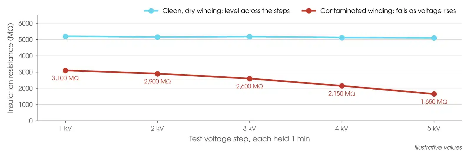
| Lower at higher voltage | A significant fall in IR with voltage may indicate insulation problems (IEEE Std 43-2013, 6.4) |
| Very high PI on old insulation | A PI above 8, for example, on asphaltic or shellac stators may mean thermal ageing and brittle insulation (IEEE Std 43-2013, 11.2) |
Is my result OK?
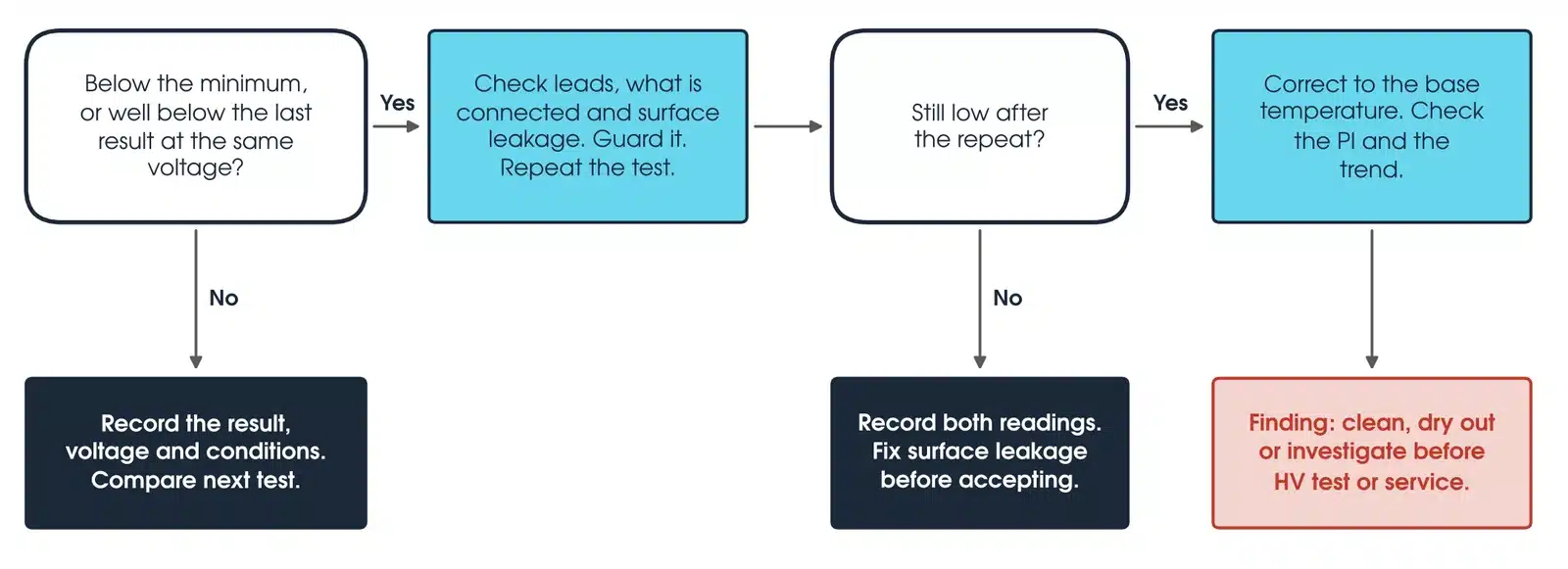
If the reading is below the minimum, or well below the last result at the same voltage, check the leads, what is connected and the surface leakage, guard the measurement and repeat it. If the repeat reads normally, record both the guarded and unguarded readings and the connection used; a guarded result that is higher shows surface leakage, which is investigated and dealt with before acceptance, not dismissed as a measurement error. If it is still low, correct it to the base temperature, check the PI and the trend, and report it as a finding to clean, dry out or investigate before any HV test or return to service.
How do I correct insulation resistance for temperature?
Insulation resistance falls as temperature rises, so correct readings to a base temperature before comparing them. For machines the base is 40 °C, and IEEE Std 43-2013 (6.3) gives Rc = KT × RT. For thermoplastic insulation KT = 0.5^((40 − T)/10); for thermosetting insulation between 10 °C and 40 °C, KT = exp[−1245 (1/(T + 273) − 1/313)].
Worked example: a thermoplastic winding reads 500 MΩ at 35 °C. KT = 0.5^0.5 = 0.707, so the corrected value is 354 MΩ at 40 °C. Transformer insulation resistance is read with the windings and liquid near 20 °C (IEEE Std C57.152-2025, 7.2.13.3), and the PI needs no temperature correction (IEEE Std 43-2013, 6.3.4).
What should an insulation resistance test report include?
The test voltage and polarity, the connection tested, the 30 second, 1 minute and 10 minute values, the PI and DAR; the winding and ambient temperature, relative humidity, dew point and time out of service (IEEE Std 43-2013, Clause 7); the minimum or criterion used, the corrected value and the change since the last test; and the instrument model, serial number and calibration date, with whether the guard was used.
What about step voltage and dielectric discharge tests?
A step voltage test raises the voltage in equal steps, holding each for 1 minute. Clean, dry insulation reads about the same at every step, and a significant fall with voltage may indicate insulation problems (IEEE Std 43-2013, 6.4); IEEE Std C57.152-2025 (7.2.13.3) gives steps typically from 1 kV to 5 kV on transformers. Megger reports that a 25% fall in resistance across a 1 to 5 voltage ratio, such as 500 V to 2500 V, usually means excessive moisture or contamination.
A dielectric discharge (DD) test measures the current still flowing 1 minute after a long charge is removed, to find one faulty layer in multilayer insulation. Megger summarises EdF's figures: a DD value below 2 is OK and above 7 is bad. Step voltage is an undervoltage test with limited power. It is not a withstand test, and it does not replace one.
Which insulation resistance tester should I use?
Match the instrument to the test voltage the plant needs. Both instruments below are available calibrated, with leads, from Megavar.
| Instrument | Test voltage | Best used for |
|---|---|---|
| Megger MIT520 5 kV | 250 V to 5 kV | Cables, transformers, switchgear and motors; PI, DAR and step voltage; to 10 TΩ |
| Megger MIT1020 10 kV | 250 V to 10 kV | Large generators and the highest voltage plant; adds dielectric discharge; to 35 TΩ |
Both instruments are available from Hobart, Launceston, Adelaide and Newcastle through Megavar's insulation resistance testing equipment hire. If you would rather have the test done, Megavar's engineers carry out high voltage testing, HV cable testing and transformer testing across Australia.
Download the insulation resistance testing guide (PDF)
Frequently Asked Questions
Is PI useful on an oil-filled transformer?
With care. IEEE Std C57.152-2025 (7.2.13.5) says PI should not be used to assess new power transformers, and the PI of insulating liquid alone is always close to 1.
How long should I discharge after a test?
At least four times the voltage application time (IEEE Std 43-2013, 6.5), then keep the item shorted and earthed until it returns to service.
Can the test damage insulation?
Rarely at the right voltage, because the tester has little energy available. Wet insulation can break down, so start at a low voltage on wet plant.
Why did two tests on the same winding differ?
Different test voltage, temperature, humidity, guarding or connected plant. Correct to the same temperature and compare like with like.
What minimum applies to CT secondaries?
IEEE Std C57.13.1-2017 (Clause 10) gives 1 MΩ as the generally accepted field minimum, and AS 61869.1:2024 (5.4.5.3) sets 200 MΩ at 1 kV DC as the product requirement where it is requested.
What is the difference between PI and DAR?
PI is the 10 minute reading divided by the 1 minute reading; DAR is the 60 second reading divided by the 30 second reading. DAR is quicker, but IEEE Std 43-2013 sets no agreed criteria for it.
Should I use the guard terminal?
Use it wherever surface leakage could affect the reading, such as a dirty bushing or a cable termination, and record that you did, so the next test is done the same way.
Does Megavar test as well as hire?
Yes. Our engineers test, commission and maintain HV plant across Australia. Call 1300 730 499.
Need an insulation resistance test done, or the instrument to do it?
Megavar tests transformers, cables, switchgear and rotating machines across Australia, and hires the insulation testers in this guide. Call 1300 730 499 or email service@megavar.com.au.