Protection relay testing proves that the relays protecting a power system will operate correctly: trip the right circuit breaker, in the right time, for a fault inside their zone, and stay stable for a fault outside it or for normal load. Everything else about a substation can be perfect and a single mis-set relay will still let a fault burn a transformer or black out a region. This guide explains the four kinds of relay test, secondary injection, primary injection, scheme testing and end-to-end testing, how often protection relays are tested, what a good test proves, and the IEC standards that apply to the relays and the testing.
Download the protection relay testing guide (PDF)

What are the basic requirements of protective relays?
Protection engineering judges a relay, and the scheme it belongs to, against five requirements, and every test is a check of one or more of them.
| Requirement | Meaning | What tests it |
|---|---|---|
| Reliability: dependability | The relay trips every time there is a fault in its zone | Secondary injection at the pickup settings; scheme trip tests; end-to-end tests |
| Reliability: security | The relay stays stable for load, inrush, disturbances and out-of-zone faults, apart from its coordinated backup duty | Injection at the stability boundary; through-fault stability tests; CT polarity and ratio checks |
| Selectivity (discrimination) | The breakers the scheme requires open, so the smallest area is lost | Grading checks against the setting study; timing tests at multiple fault levels |
| Speed | The fault is cleared before equipment is damaged or the system loses stability | Operating time measurement at the setting multiples; trip circuit timing |
| Sensitivity | The relay detects the minimum fault current its zone can produce, including high resistance earth faults | Pickup tests at the minimum setting; earth fault element tests |
Simplicity and economy are often added as a sixth and seventh. A scheme that is hard to understand is hard to test and hard to maintain, and a scheme that is more elaborate than the asset warrants costs more in testing over its life than it saves.
How is relay testing done?
Relay testing is done by injecting currents and voltages that represent faults into the relay, or into the primary circuit it protects, and measuring whether the relay picks up, trips and resets at the values and times its settings require. There are four levels; end-to-end testing applies where a scheme spans two substations.
Secondary injection testing
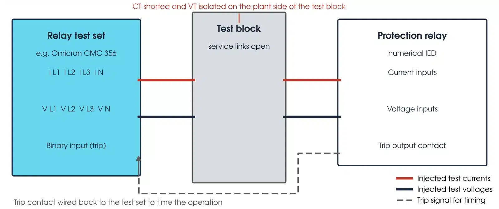
Secondary injection applies test currents and voltages directly to the relay's secondary terminals, in place of the CT and VT secondaries, from a relay test set such as the Omicron CMC 356. The test set generates three-phase currents and voltages with controlled magnitude, angle and frequency, steps or ramps them to find the pickup and drop-off of each element, applies fault shots to measure operating time, and records the relay's binary outputs. For a numerical relay the test plan is built from the setting file and typically covers every enabled element: overcurrent and earth fault pickups and time curves, distance zone reaches and times on the impedance plane, differential slope and pickup, under and over voltage and frequency, directional elements and their polarising, breaker failure, and auto-reclose sequences. Megavar records results in Omicron Test Universe and compares them with the approved protection settings, the manufacturer's specification and the relevant standards, so the test is repeatable.
Primary injection testing
Primary injection passes a real current through the primary conductor, from a high current set such as the Omicron CPC 100, so that the current flows through the CTs, the secondary wiring and the relay together. It proves the whole measuring chain: CT ratio and polarity, the wiring from the CT to the relay including any shorting links and test blocks, and the relay's measured value, all in one test. Before energisation, it is the test that catches a crossed CT phase or a CT wired to the wrong relay. Secondary injection cannot see those faults because it bypasses the CT.
What is the difference between primary and secondary current injection testing?
Secondary injection tests the relay; primary injection tests the relay and the CT circuit that feeds it. Secondary injection puts test currents and voltages into the relay through the test block, so it proves every element against its setting but bypasses the CTs. Primary injection puts current through the primary conductor, so the CTs, the secondary wiring and the relay all carry it, which proves CT ratio, polarity and wiring but not the full setting characteristic. A complete commissioning uses both.
| Secondary injection | Primary injection | |
|---|---|---|
| Current goes into | The relay, through the test block, in place of the CT and VT secondaries | The CT primary; the CT's secondary current then flows through the wiring and the relay |
| What it proves | Every enabled element at its setting and operating time | CT ratio, polarity and the wiring from the CT to the relay |
| What it cannot see | A crossed CT phase or a CT wired to the wrong relay | CT performance at fault level: it checks ratio at the test current |
| Typical test set | Omicron CMC 356 | Omicron CPC 100 |
What is a primary injection test?
A test that passes current through the CT primary to prove ratio, polarity and wiring through to the relay; the CT testing guide covers it in full.
Scheme and trip testing
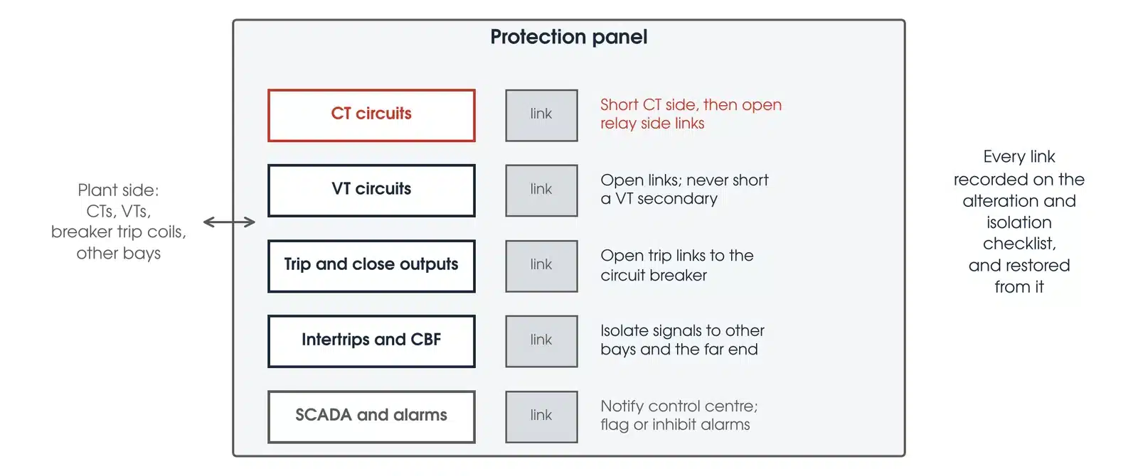
Scheme testing proves the logic and the wiring between the relays and the circuit breakers: that a trip from each element reaches the right breaker through the right trip coil, that the trip circuit supervision works, that intertrips, blocking signals and breaker fail initiations go where the scheme drawing says, and that the alarm and SCADA indications are correct. Under the agreed outage, the breaker is tripped for real, from the relay, for every trip path on the drawing, and the operating time from relay output to breaker main contacts is recorded.
End-to-end testing
Line differential and permissive distance schemes have relays at both ends of a line that must agree on the fault. End-to-end testing injects the same simulated fault at both substations at the same instant, synchronised by GPS using a unit such as the Omicron CMGPS 588, and confirms the two relays trip together for an in-zone fault and restrain together for an external one. It also proves the communications channel, its latency and its failure modes. End-to-end testing is part of transmission substation commissioning, and it is the final proof that a new line protection scheme works as a system.
IEC 61850 schemes
In an IEC 61850 substation the trip, block and interlock signals travel as GOOSE messages over the station bus, and in process bus designs the CT and VT values arrive as Sampled Values. Testing then includes subscribing to and publishing GOOSE with the test set, isolating physical outputs and GOOSE or Sampled Values paths to the approved isolation plan and verifying publisher and subscriber test behaviour (relay test mode alone is not an isolation), and, in process bus schemes, injecting Sampled Values streams directly from the test set. The Omicron CMC 500 with IEDScout in Megavar's hire fleet supports GOOSE testing and, as an option, Sampled Values.
How often should protection relays be tested?
The interval is set by the asset owner's protection maintenance policy. TasNetworks, for example, sets routine test intervals for its secondary equipment in its asset management plan. The intervals depend on the relay technology, because a numerical relay supervises itself continuously and an electromechanical relay does not. The US Bureau of Reclamation publishes a time-based schedule, FIST 3-8, that is a useful reference:
| Relay technology | Functional test interval (USBR FIST 3-8) | Reason |
|---|---|---|
| Electromechanical | Every year in harsh conditions, every 2 years in controlled environments | No self-supervision; springs, bearings and contacts drift and stick |
| Static (analogue electronic) | Every 2 years | Component ageing; limited self-checking |
| Microprocessor, unmonitored | Every 4 years | Self-supervision covers the processor and memory but not the measuring inputs, output contacts or trip wiring |
| Microprocessor, monitored (self-test alarm, power supply, trip coil and DC supply monitored and alarmed) | Every 6 years | Most failure modes are alarmed; the test confirms what the monitoring cannot see |

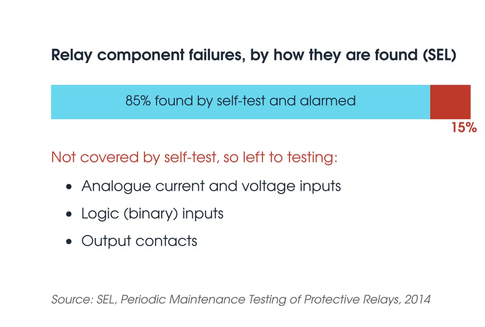
FIST 3-8 also sets a first test 1 year after commissioning, and a retest after any setting change, repair or firmware update. SEL's guidance goes further for relays whose self-test alarm is monitored in real time: SEL reports that its self-tests detect about 85% of component failures, and recommends testing the inputs, outputs and measuring that self-test does not cover at a longer interval, for example once every ten years. These are published references, not Australian requirements; FIST 3-8 also verifies inputs and outputs every 2 years. Megavar's protection relay testing service covers commissioning, routine testing, and retesting after setting changes and firmware upgrades.
What is the IEC standard for protection relay testing?
What is the IEC standard for protection relays?
The IEC 60255 series, Measuring relays and protection equipment, is the standard for protection relays. Part 1, IEC 60255-1:2022, is adopted in Australia, with modifications, as AS/NZS 60255.1:2025 and sets the common requirements. The manufacturer declares the assigned error, and the measured error must be within it, allowing for test set uncertainty (clause 6.5.2.1); pickup and operate time are verified from five consecutive measurements (clauses 6.5.2.2 to 6.5.2.4). The functional parts define how each protection function is specified and how its accuracy and operating time are tested: IEC 60255-151 for overcurrent, IEC 60255-121 for distance, IEC 60255-187-1 for differential, IEC 60255-127 for over and under voltage, IEC 60255-181 for frequency, and IEC 60255-149 for thermal. Other parts of the series cover the product type tests the relay must pass. When a test plan sets the tolerance for an overcurrent element, that figure is the accuracy the manufacturer declares under IEC 60255-151, taken from the relay manual.
IEC 61850 governs communications between relays and the rest of the substation, and its conformance and interoperability testing is separate from functional protection testing. In Australia, the network operator's protection and testing standards set the test plan content and the acceptance criteria for connection to their network, as TasNetworks' Secondary Equipment Testing Standard does.
Australian standards for the instrument transformers and the people
A relay can only be as accurate as the CTs and VTs that feed it. AS 61869.2 Table 205 sets the protective CT classes: 5P allows a ratio error of plus or minus 1 per cent and 60 minutes of phase displacement at rated current and a composite error of 5 per cent at the rated accuracy limit current; 10P allows plus or minus 3 per cent and a 10 per cent composite error. Standard accuracy limit factors are 5, 10, 15, 20 and 30, and a PR core limits remanence to 10 per cent (clause 5.6.202.3). Class PX CTs, used for differential schemes, are specified instead by knee point e.m.f., exciting current and turns ratio error of no more than 0.25 per cent (clause 5.6.202.4). AS 61869.2 defines the knee point as the voltage that, increased by 10 per cent, raises the exciting current by 50 per cent (clause 3.4.215); the IEEE 45 degree knee point (IEEE C57.13-2016 clause 6.10.2) reads lower, and IEEE C37.110-2023 puts the difference at about 20 to 25 per cent (clause 4.3.2). IEEE C57.13.1-2017 covers field testing of relaying CTs. AS 61869.3 Table 302 sets protective VT classes 3P and 6P at plus or minus 3 and 6 per cent voltage error from 5 per cent of rated voltage up to the rated voltage factor.
AS 2067 clause 2.1.1 requires installation, testing, commissioning and maintenance of substations and HV installations to be carried out by personnel qualified and competent in the discipline. It does not set a test interval; that stays with the asset owner.
What is the best way to test a relay?
The best way to test a relay is a secondary injection test built from the relay's own setting file, run with a three-phase test set under automated test software, followed by primary injection through the CTs and a trip test of every path to the breaker. The setting-file approach matters because a test built from a generic template checks the elements the template author thought of; a test built from the setting file checks every element that is actually enabled, at the values actually set. Automated software makes the test repeatable and leaves a record that the next engineer can rerun. Megavar's engineers run this method on the Omicron CMC 356 with Test Universe. The CMC 356 and CMC 500, with the Megger SVERKER 760 for single-phase work, are available from the relay testing rental range and the wider Omicron hire range.

What a protection relay test report should contain
A relay test is only as good as the record it leaves. An asset owner should expect the following in a protection relay test report from any tester. TasNetworks' Secondary Equipment Testing Standard sets similar requirements for work on its network.
- Relay identity: make, model, firmware version, serial number, location and the setting file name and version tested.
- The applied settings, printed from the relay, not copied from the setting study, so a mismatch between the two is visible.
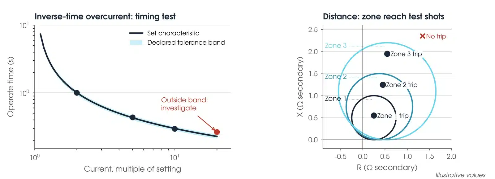
- For every enabled element: the pickup, drop-off and operating time at each test point, the expected value from the setting, the tolerance from the assigned error the relay manual declares (AS/NZS 60255.1 clause 6.5.2.1), and a pass or fail.
- Distance relays: the measured zone reaches plotted on the impedance plane against the set characteristic.
- Differential relays: the measured slope and pickup against the set characteristic, and the through-fault stability result.
- CT ratio and polarity from primary injection, VT ratio and polarity, and the secondary wiring checks.
- Trip and scheme tests: every trip path on the drawing, with the breaker operating time, trip circuit supervision, intertrips and alarms proven.
- End-to-end test results with the communications channel delay.
- Any deviation from the setting study, any defect found and how it was closed, and the signature of the test engineer.
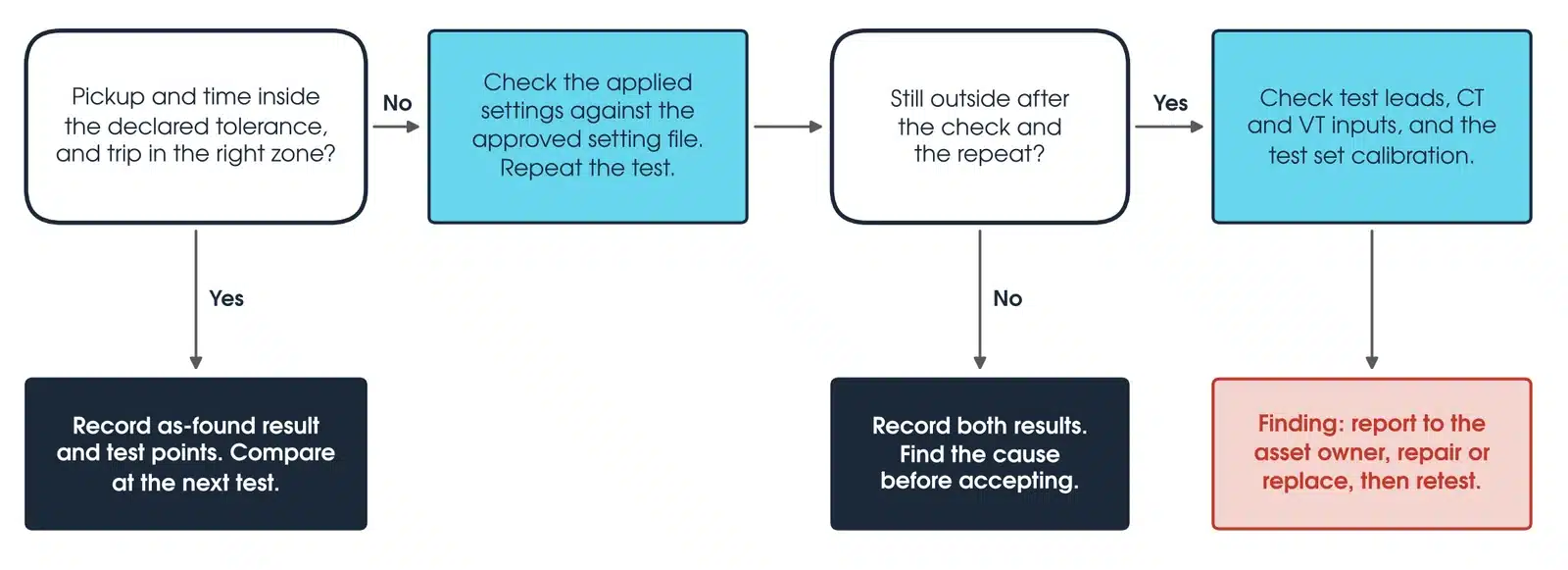
A report that lists only 'tested OK' against each relay does not allow the next test to be compared with this one, and it is the comparison over time that shows a relay beginning to drift. Megavar tests protection schemes for substations, transmission networks, renewable energy projects, industrial HV systems and mining sites across Australia.
Download the protection relay testing guide (PDF)
Frequently Asked Questions
How often should protection relays be tested?
The asset owner's protection maintenance policy sets the interval. As a published reference, USBR FIST 3-8 gives every 1 to 2 years for electromechanical relays, 2 years for solid-state relays, functional tests every 4 years for unmonitored and 6 years for monitored microprocessor relays, with a first test 1 year after commissioning. Any setting change, firmware update or repair calls for a retest.
What is the IEC standard for protection relay testing?
The IEC 60255 series, Measuring relays and protection equipment. IEC 60255-1, adopted in Australia as AS/NZS 60255.1:2025, gives the common requirements and the functional parts define the accuracy and operating time tests for each protection function: 60255-151 overcurrent, 60255-121 distance, 60255-187-1 differential, 60255-127 voltage, 60255-181 frequency and 60255-149 thermal. IEC 61850 covers substation communications and its conformance testing separately.
How is relay testing done?
By injecting currents and voltages that represent faults and measuring whether the relay picks up, trips and resets at the set values and times. Secondary injection from a test set such as the Omicron CMC 356 tests every enabled element against the setting file. Primary injection passes real current through the CTs to prove the whole measuring chain. Scheme testing trips the breaker from each relay element through every trip path. End-to-end testing injects synchronised faults at both ends of a line to prove the scheme as a system.
What are the basic requirements of protective relays?
Reliability, split into dependability (it trips for every in-zone fault) and security (it stays stable for load and out-of-zone faults, apart from coordinated backup); selectivity, so only the breakers the scheme requires open; speed, so the fault clears before damage or instability; and sensitivity, so the minimum fault the zone can produce is detected. Simplicity and economy are usually added. Every relay test checks one or more of these.
What is the best way to test a relay?
A secondary injection test built from the relay's own setting file and run under automated test software on a three-phase test set, so every enabled element is tested at its actual setting and the result is repeatable, followed by primary injection through the CTs and a trip test of every path to the circuit breaker. Megavar runs this method on the Omicron CMC 356 with Test Universe.
What is the IEC standard for protection relays?
IEC 60255, Measuring relays and protection equipment, with Part 1 adopted in Australia as AS/NZS 60255.1:2025. The series defines the common requirements, the environmental and EMC type tests, and the functional requirements and accuracy classes for each protection function.
Which relay test equipment does Megavar hire?
Megavar's hire fleet includes the Omicron CMC 356 for three-phase secondary injection, the CMC 500 with IEDScout for IEC 61850 GOOSE and optional Sampled Values testing, the CMGPS 588 for GPS-synchronised end-to-end tests, the CPC 100 for primary injection and CT testing, and the Megger SVERKER 760 for single-phase work. All are available from Megavar's relay testing and Omicron hire ranges.
Does Megavar test IEC 61850 protection schemes?
Yes. Megavar verifies protection scheme logic including IEC 61850 GOOSE messaging, alongside hardwired intertripping and permissive signalling, with physical outputs and GOOSE paths isolated to the approved plan; relay test mode alone is not an isolation.
What is a primary injection test?
A test that passes a known current through the primary circuit of a CT, typically hundreds of amps at a few volts, and reads the current at the relay. It proves CT ratio, polarity and the wiring through to the relay, which secondary injection cannot see because it bypasses the CT.
What is the difference between primary and secondary current injection testing?
Secondary injection puts test currents and voltages into the relay through the test block and proves every element against its setting. Primary injection puts current through the primary conductor, so the CTs, wiring and relay all carry it, and proves CT ratio, polarity and wiring. A complete commissioning uses both.
Commissioning or maintaining protection relays?
Megavar commissions and routine-tests protection schemes across Australia from 11 kV distribution to 500 kV transmission, and hires the Omicron CMC relay test sets its engineers use. Call 1300 730 499 or email service@megavar.com.au.