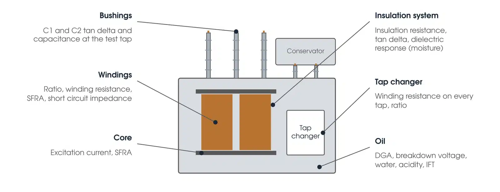
Transformer testing is a defined set of electrical, dielectric and oil tests that together prove a power transformer is built as specified, has arrived undamaged, is safe to energise, and remains in good condition through its service life. No single test proves all of that. Each one checks a different part of the transformer: the windings, the core, the insulation system, the bushings, the tap changer and the oil. This guide lists the tests in the order they are run on site, explains what each one proves, gives the limits that the standards and accepted practice set, and answers the questions asset owners ask most often about whether a transformer is good or bad.
Download the transformer testing guide (PDF)

Why transformer testing is done in stages
A power transformer is tested at four points in its life, and the tests at each point have a different purpose.

| Stage | Purpose | Typical tests |
|---|---|---|
| Factory acceptance (FAT) | Prove the unit meets the specification and IEC 60076 before it leaves the works | Routine tests to IEC 60076-1 and 60076-3: ratio, resistance, vector group, no-load and load losses, impedance, applied and induced voltage with PD measurement, plus any type and special tests ordered |
| Pre-commissioning on site (SAT) | Prove nothing was damaged in transport or assembly and that the installed unit matches the FAT results | Ratio, winding resistance, vector group, insulation resistance and polarisation index, tan delta of windings and bushings, excitation current, SFRA, leakage reactance, oil tests, CT tests, protection and cooling checks |
| Energisation and in-service checks | Confirm the transformer and its protection behave correctly under voltage and load | Soak at no load, Buchholz and gas checks, on-load checks of tap changer, temperature and cooling, Baseline DGA before energisation and a follow-up sample after energisation, then on the routine cycle (IEEE C57.152-2025, Table 1) |
| Condition assessment in service | Track degradation and decide on maintenance, refurbishment or replacement | DGA and oil quality trending, tan delta and DFR, SFRA against the fingerprint, bushing tests, winding resistance and OLTC checks, thermography |
The site tests are compared with the factory results, not just against a limit. A ratio or SFRA result that is inside tolerance but different from the FAT record still means something moved in transit, and That is treated as a finding, not a pass.
The electrical tests and what each one proves
Turns ratio and vector group
The ratio test applies a voltage to one winding and measures the induced voltage on the other, on every tap. It proves the windings have the right number of turns, that no turns are shorted, and that the tap changer connects the taps it says it does. IEEE C57.12.00-2021 clause 9.1 requires the voltages of all windings and all tap connections to be within 0.5 per cent of the nameplate voltages, and IEEE C57.152-2025 clause 7.2.10 applies the same 0.5 per cent in the field. Clause 9.1 allows the nearest turn where 0.5 per cent is less than one turn and exempts reactance-type bridging taps, so confirm the manufacturer's expected ratios before rejecting a tap. For a new transformer at acceptance, AS/NZS 60076.1 Table 1 sets the lower of ±0.5 per cent and one tenth of the measured percentage impedance on the principal tapping, and ±0.5 per cent of the design turns ratio on the other tappings. The vector group test confirms the phase displacement between HV and LV (Dyn11, YNd1 and so on) matches the nameplate, which matters because a transformer paralleled with the wrong vector group circulates fault-level current. Both tests run on the OMICRON CPC 100 one phase at a time, or on the TESTRANO 600, which measures all three phases from one connection.
Winding resistance
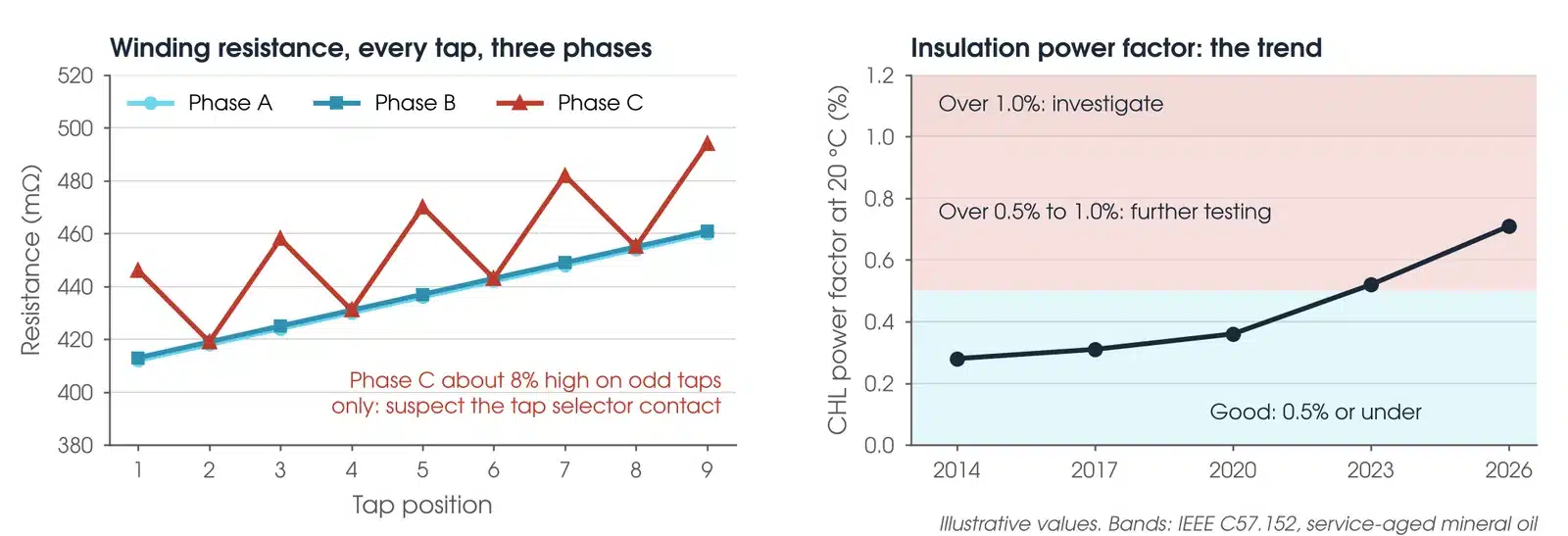
A DC current is passed through each winding on each tap and the resistance measured. It proves the conductor, the brazed joints, the leads and the tap changer contacts are sound. IEEE C57.152-2025 clause 7.2.7 expects the phases to agree within 2 per cent of each other, and treats agreement within 5 per cent in any comparison, such as against the factory value once both are corrected to the same temperature, as usually satisfactory; a phase outside that, or a tap that reads high relative to its neighbours, points to a loose connection or a burnt tap changer contact. IEEE C57.12.90-2021 clause 5.1 takes the winding temperature as the average oil temperature only after 3 hours without excitation (1 hour with pumps running) and with top and bottom oil within 5 °C. On a large transformer the test takes time because the core must saturate before the reading stabilises, and the winding must be fully discharged afterwards. The DC current also leaves the core magnetised, so winding resistance is run after the excitation current and SFRA tests, and the core is demagnetised before energisation.
Insulation resistance and polarisation index
A 5 kV or 10 kV insulation resistance tester, such as the Megger MIT1020 10 kV, measures the resistance between each winding and earth and between windings. The polarisation index (PI) is the ratio of the 10 minute reading to the 1 minute reading. Insulation resistance shows there is no gross insulation fault before the higher voltage tests. It is never measured while the transformer is under vacuum (IEEE C57.12.90-2021 clause 10.11). On a service-aged transformer, IEEE C57.152-2025 clause 7.2.13.5 grades a PI under 1.0 as dangerous, 1.0 to 1.1 poor, 1.1 to 1.25 questionable, 1.25 to 2.0 fair and above 2.0 good. The same clause says the PI should not be used to assess a new power transformer, because the PI of the oil itself is always close to 1 and can be low even when the insulation is good. Insulation resistance varies with voltage and temperature, so it is compared only at the same test voltage and recorded with the oil temperature. The core insulation is checked the same way with the core earth strap lifted: IEEE C57.152-2025 Table 6 gives over 500 MΩ as typical for a new unit, over 100 MΩ as normal in service and under 10 MΩ as needing investigation.
Dissipation factor (tan delta) and capacitance
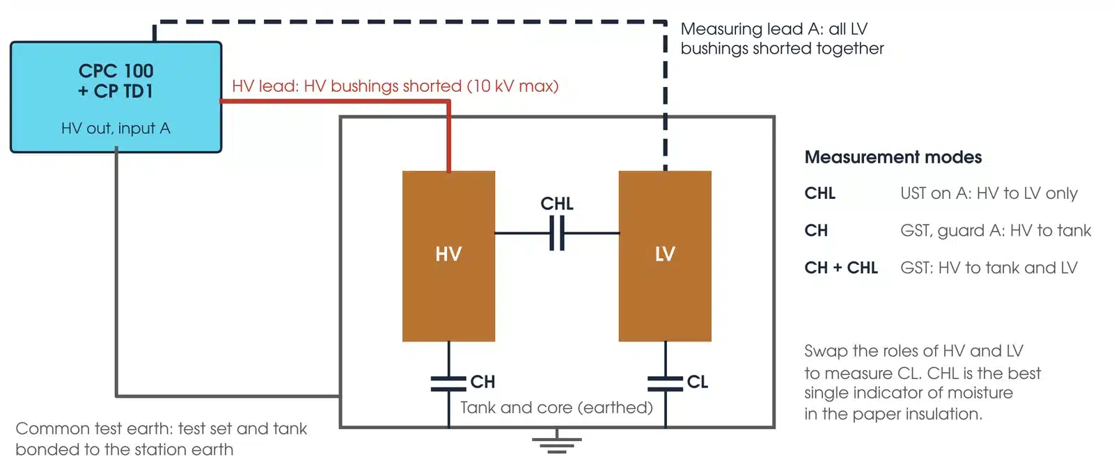
Tan delta measures the dielectric loss in the insulation between windings and between each winding and the tank, with a test set such as the Omicron CP TD1 on the CPC 100. IEEE C57.12.90-2021 clause 10.10.3 caps the test voltage at 10 kV, or half the applied voltage test level if that is lower. It proves the overall insulation system is dry and uncontaminated. For a mineral oil transformer at 20 °C, IEEE C57.152-2025 Table 15 gives 0.5 per cent or under for a new unit (0.4 per cent at 230 kV and above); on a service-aged unit, over 0.5 up to 1.0 per cent calls for further testing and over 1.0 per cent for investigation. IEEE C57.12.90-2021 clause 10.10.4 says the power factor is reported as measured with the top oil temperature. Where a value at 20 °C is needed for the C57.152 limits, the correction method and its basis are stated and the corrected value is reported separately; no universal correction curve is applied. A rising trend between tests is more significant than the absolute figure. Capacitance is measured at the same time and compared with the factory value; a change in capacitance can mean the geometry of the winding has changed.
Bushing tests
Condenser bushings carry a test tap that allows the main insulation (C1) and the tap insulation (C2) to be measured for capacitance and tan delta separately from the winding. C2 is tested at the manufacturer's lower tap voltage, never at the C1 voltage, with the other taps earthed, and each tap is re-earthed and its cover refitted before energisation. A CVT also uses C1 and C2, for its capacitor divider, with different connections: the VT testing guide covers it. IEEE C57.152-2025 clause 7.3 notes that bushings are inexpensive compared with the transformer, but their failure can cause the complete loss of it, and has been known to cause fire, explosion and damage from projectile fragments, so each one is tested on its own. The same clause, summarising IEEE C57.19.100, calls for more frequent testing or removal when the power factor reaches 1.5 to 2 times its initial reading, and removal from service when it triples. A capacitance more than 5 per cent from nameplate is questionable and more than 10 per cent unacceptable, a sign of shorted condenser layers (OMICRON); IEEE C57.19.100-2025 clause 10.4.1 treats a capacitance increase of 5 per cent or more as cause to investigate. AS/NZS 60137:2020 Table 8 (clause 9.2.3) sets a maximum tan delta of 0.007 (0.7 per cent) at 1.05 Um/√3 for new oil-impregnated paper, resin-impregnated paper and resin-impregnated synthetic bushings; this is the factory routine test acceptance limit, not an in-service pass level.
Excitation current
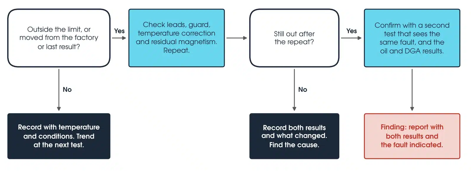
A single-phase voltage, typically 10 kV, is applied to each HV phase in turn with the other windings open and the current measured. It proves the core and the winding turn insulation are sound. IEEE C57.152-2025 clause 7.2.11 gives the expected pattern on a three-limb core as two similar higher readings on the outer phases and a lower reading on the centre phase (high, low, high); a four-limb core gives low, high, low, and a five-limb or shell core with a non-delta secondary gives three similar readings. A phase that breaks the expected pattern points to shorted turns or a core problem, or to residual magnetism from an earlier DC test, which is why the core is demagnetised and the test repeated before a fault is called.
Sweep frequency response analysis (SFRA)
SFRA injects a low voltage sweep into each winding and records the transfer function. AS/NZS IEC 60076.18 clause 4.5 sets the lowest frequency at 20 Hz or below and the highest at no less than 1 MHz for windings above 72.5 kV and 2 MHz at or below 72.5 kV, and recommends at least 2 MHz for all. The trace is a fingerprint of the mechanical geometry of the core and windings. Compared with the factory trace, or between phases, it shows whether the core or windings have moved in transport or deformed under a through fault. Agreement does not prove the absence of every defect. The standard sets out the measurement method; interpretation is informative guidance only and there is no pass or fail limit: the result is a comparison. SFRA should be run before energising any transformer that has travelled, and Megavar hires the OMICRON FRANEO 800 for it.
Leakage reactance and short circuit impedance
Short circuit impedance is measured per phase with the LV shorted and compared with the nameplate and the FAT record. IEEE C57.152-2025 clause 7.2.12 sets a three-phase equivalent result within 3 per cent of the nameplate, and each per-phase result within 3 per cent of the average of the three phases. A change is a sign of winding movement, and it is the second test, after SFRA, that catches transport damage.
Dielectric frequency response (DFR)
DFR, measured with an instrument such as the Omicron DIRANA, measures tan delta across a frequency range from millihertz to kilohertz and models the result to give the moisture content of the solid insulation (OMICRON). It estimates paper moisture from a dielectric response model, and IEEE C57.152-2025 Table 1 lists it as an as-needed test at commissioning and in service.
Dielectric tests: applied voltage, induced voltage and partial discharge
The applied voltage test (separate source AC withstand) and the induced voltage test are routine tests under AS/NZS 60076.3 (IEC 60076-3) Table 1 and are normally performed in the factory; the induced voltage test with PD measurement is routine for windings above 72.5 kV and a special test at or below it. The induced voltage test with partial discharge measurement (IVPD) is the most searching test a transformer undergoes: the winding is excited at an elevated frequency to raise the voltage to the enhanced level without saturating the core, and the partial discharge is measured at the bushing taps throughout. Under AS/NZS 60076.3 clause 11.3.5 the test is valid only if the background is no more than 50 pC at the start and end, and it passes if the voltage does not collapse, no PD level in the one hour period exceeds 250 pC, the level shows no rising trend and rises by no more than 50 pC, and the level at 1.2 Ur/√3 after the one hour period is no more than 100 pC. A failure on PD does not by itself reject the transformer; it leads to agreed investigation. After a repair, clause 8 requires the IVPD at 100 per cent of the original test level. The purchase specification may set tighter values. Megavar witnesses these tests at the factory on its customers' behalf.
Transformer oil testing and dissolved gas analysis
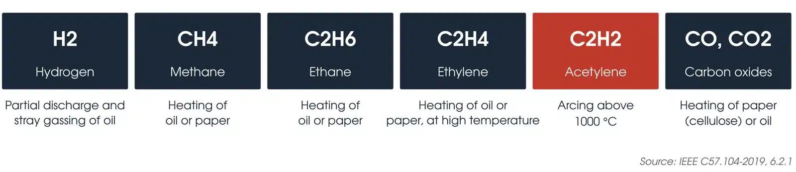
Oil is sampled to AS 1767.2.3 (IEC 60475) and tested for dielectric breakdown strength (AS 1767.2.1, IEC 60156), moisture by Karl Fischer titration (AS 1767.2.8, IEC 60814), acidity, interfacial tension and dissipation factor. Together these prove the oil is dry, clean and able to insulate and cool. AS 60422 Table 5 sets good, fair and poor values for each test by equipment category; for categories O and A, a breakdown voltage over 60 kV and water under 15 mg/kg are good. For oil in a new transformer before energisation, Table 3 sets a breakdown voltage over 60 kV and water under 10 mg/kg above 72.5 kV. Dissolved gas analysis (DGA) measures the hydrogen, methane, ethane, ethylene, acetylene, carbon monoxide and carbon dioxide dissolved in the oil, and IEEE C57.104-2019 gives the interpretation for mineral oil transformers (AS 60422 places DGA outside its scope). Under clause 6.2.1, hydrogen comes mainly from partial discharge and stray gassing of the oil, methane, ethane and ethylene from heating of oil or paper, acetylene from arcing at above 1000 °C, and carbon oxides from heating of the paper or oil; a transformer without internal fuses, switches or other arcing devices should create no acetylene in normal operation. A baseline DGA sample is taken before energisation, a follow-up sample after energisation, then samples on the routine cycle (IEEE C57.152-2025, Table 1) for the life of the transformer. The laboratory reports a status under IEEE C57.104-2019: probably normal, possibly suspicious or probably suspicious. Its Table 1 90th percentile values for acetylene are 1 to 2 µL/L, and under Table 3 any increase in acetylene between samples is significant. A rising gas trend is the earliest warning most transformers give.
How do you check your transformer?
In service, a transformer is checked on two cycles. The routine cycle is a dissolved gas analysis and oil quality sample, with a check of oil level, winding and oil temperature, breather condition and cooling plant, and a walk-round for leaks, bushing damage and corrosion. AS 60422 Table 4 recommends the routine oil tests every 1 to 2 years for category O, 1 to 3 for A, 1 to 4 for B and 2 to 6 for C, shortened when a result is fair or poor. The outage cycle, at the asset owner's maintenance interval, repeats the electrical tests above: insulation resistance, winding and bushing tan delta and capacitance, winding resistance, turns ratio and SFRA, each compared with the previous record. The comparison with the previous record is the check; a reading that is inside the limit but has moved since last time is the earliest warning the transformer gives.
What is CT and PT test?
A CT and PT test checks the current transformers and voltage (potential) transformers built into the transformer bushings and turrets, or installed in the adjacent switchgear, which the protection and metering depend on. For each current transformer the tests are ratio and polarity, excitation (magnetisation) curve to find the knee point, secondary winding resistance, insulation resistance and secondary circuit burden, to AS 61869.2:2021. For a voltage transformer the tests are ratio and polarity, insulation resistance and, where accessible, tan delta, to AS 61869.3:2021. The results prove that the protection relays will see the correct current and voltage and that a CT will not saturate before the relay has operated. The CPC 100 injects the primary current and drives the excitation test from the same unit, and these tests are part of every substation commissioning programme.
How to test a transformer
How to test a transformer depends on the stage, but the order of the tests matters at every stage. Inspect the transformer and take the oil sample first. Run the AC tests that are sensitive to core magnetisation, tan delta, excitation current and SFRA, before winding resistance, because the DC current in a resistance test leaves the core magnetised. Make a quick insulation resistance check before tan delta, with the full timed test later in the sequence, and stop if the current rises without settling. Compare every result with the nameplate, the factory record and the other phases, and demagnetise the core before the transformer is energised. The full site sequence for a three-phase power transformer is below.

How to test a 3 phase transformer?
A three-phase power transformer on site is tested in this order. Inspection and oil come first, the AC tests sensitive to core magnetisation come before any DC test, and the core is demagnetised after winding resistance.
- Visual and mechanical: nameplate against the drawings, oil level, breather, pressure relief, Buchholz, bushings, earthing of the tank and core, and the transport impact recorder.
- Oil sample for breakdown strength, moisture and baseline DGA.
- Quick insulation resistance check on each winding before any voltage above 1 kV is applied.
- Tan delta and capacitance of the windings, and C1 and C2 of each bushing (C2 at its tap rating).
- Excitation current, typically at 10 kV, each phase.
- SFRA on each winding, compared with the factory fingerprint.
- Leakage reactance or short circuit impedance per phase, compared with the nameplate.
- Insulation resistance and polarisation index on each winding to earth and between windings, never under vacuum.
- Turns ratio and vector group on every tap, three phases.
- Winding resistance on every tap, three phases, temperature corrected, then demagnetise the core.
- CT ratio, polarity, excitation curve, winding resistance and insulation resistance on every bushing and neutral CT.
- Tap changer operation through the full range, motor drive, limit switches and tap position indication at the control panel.
- Cooling, temperature indicators, Buchholz, pressure relief and oil level alarms injected and proven through to the protection scheme.
- Energise at no load, soak, check gas, then take the post-energisation DGA.
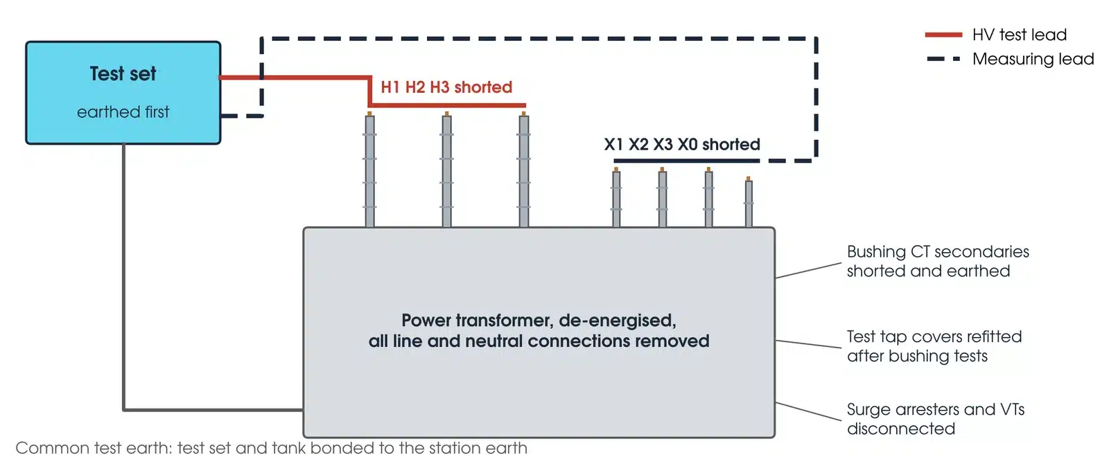
The OMICRON CPC 100 and TESTRANO 600 run most of this sequence, and both are available from Megavar's transformer testing rental range for contractors and asset owners who do their own commissioning.
How do you check if a transformer is bad?
A transformer is judged bad when a test result is outside its standard limit, or when a result has moved from its own earlier record by more than the test's normal scatter. The second condition catches more faults than the first. The indicators Megavar engineers weigh, in rough order of how often they condemn a unit, are:
| Indicator | Threshold that calls for action | What it points to |
|---|---|---|
| Dissolved gas analysis | Any increase in acetylene between samples; a rising ethylene or hydrogen trend; DGA Status 2 or 3 under IEEE C57.104-2019 | Arcing, overheating or partial discharge inside the tank |
| Bushing C1 tan delta and capacitance | Power factor 1.5 to 2 times its initial reading (test more often or remove) or three times (remove), per IEEE C57.152-2025; capacitance over 5 per cent from nameplate (over 10 per cent: unacceptable) | Deteriorated or shorted condenser layers; a failure risk |
| Winding tan delta | Over 0.5 per cent at 20 °C on a new unit; over 1.0 per cent in service; or a rising trend | Moisture or contamination in the main insulation |
| Turns ratio | Deviation above 0.5 per cent from nameplate, or any tap out of family | Shorted turns or a tap changer fault |
| Winding resistance | Phases more than 2 per cent apart on the same tap, or more than 5 per cent from the factory value after temperature correction | Loose joint, burnt tap changer contact, broken strand |
| SFRA | Trace that no longer matches the factory fingerprint, the other phases or a sister unit | Winding movement or deformation |
| Insulation resistance and PI | PI below 1.25 on a service-aged unit, with low absolute resistance | Wet insulation |
| Oil moisture and breakdown | Water or breakdown voltage in the AS 60422 poor band for the equipment category | Wet or contaminated oil, often with wet paper behind it |
How to check a transformer using a multimeter?
A multimeter can confirm continuity through each winding and give a rough comparison of winding resistance between phases on a small dry-type or distribution transformer, and it can confirm the windings are not shorted to each other or to the frame. That is the limit of what it proves. It cannot measure insulation resistance at a meaningful voltage, cannot measure ratio on a power transformer with any accuracy, and cannot see the dielectric and oil condition that decides whether a transformer is fit for service. For anything above a few hundred kVA the minimum is an insulation resistance tester and a turns ratio tester, and for a power transformer the full set described above.
What is CVT testing?
CVT testing covers the capacitor voltage transformers used for metering and protection on transmission networks. A CVT divides the line voltage through a capacitor stack and an electromagnetic unit, and it is tested for ratio and polarity, for the capacitance and tan delta of each capacitor section (the test that finds failing capacitor elements), for insulation resistance and for secondary burden. A ratio error that drifts, or a significant or abrupt change in section capacitance against its baseline and the other phases, can indicate failed capacitor elements; the manufacturer's criteria decide. The VT testing guide covers CVT connections in detail. CVTs are tested with the CPC 100 and CP TD1.
What is the procedure for performing a transformer magnetic balance test?
The magnetic balance test is a quick core check on a three-phase transformer. A single-phase low voltage (230 V is common) is applied to one phase of the HV winding and the induced voltage on the other two phases is measured. On a healthy three-limb core, energising the centre phase gives roughly equal voltages on the two outer phases, and energising an outer phase gives a higher voltage on the adjacent phase than on the far one. Compare the two induced voltages with the distribution expected for the core and winding connection. A phase that induces much less than expected, or no voltage, points to shorted turns or a core fault. It is a screening test rather than a standard test and is normally run alongside the excitation current test rather than instead of it.
Standards that govern transformer testing in Australia
| Standard | Scope |
|---|---|
| IEC 60076 series (adopted as AS/NZS 60076) | Power transformers: AS/NZS 60076.1:2014 general requirements, tolerances and routine tests; AS/NZS 60076.3:2017 Amd 1:2020 insulation levels and dielectric tests, including the IVPD acceptance criteria; AS/NZS IEC 60076.18:2025 frequency response measurement |
| IEC 60599 | Interpretation of dissolved and free gas analysis; the IEC counterpart to IEEE C57.104 |
| AS 60422:2017 (IEC 60422) | Mineral insulating oils: supervision and maintenance guidance and in-service limits |
| AS 1767.2.1, AS 1767.2.8, AS 1767.2.3 (IEC 60156, IEC 60814, IEC 60475) | Oil breakdown strength, moisture by Karl Fischer, oil sampling |
| IEC 61869-1, -2, -3 | Instrument transformers: general, current transformers, inductive voltage transformers |
| IEEE C57.152-2025 | Guide for diagnostic field testing of liquid-filled power transformers, regulators and reactors; the field limits for ratio, winding resistance, power factor, impedance, PI, core insulation and bushing power factor trend |
| AS 2067 | Substations and high voltage installations exceeding 1 kV a.c. |
| IEEE C57.104-2019 | Interpretation of gases generated in mineral oil-immersed transformers; the DGA status the laboratory reports |
| IEEE C57.12.90-2021 | Test code for liquid-immersed transformers: clause 5 winding resistance temperature stability and correction, clause 10.10 insulation power factor test voltage and temperature reporting |
| IEEE C57.12.00-2021 | General requirements for liquid-immersed transformers: clause 9.1 ratio tolerance of 0.5 per cent on all windings and tap connections |
Megavar's transformer testing service covers power transformers from 11 kV distribution class to 500 kV transmission class, for commissioning, routine maintenance, condition assessment and post-fault investigation, and Megavar witnesses factory acceptance tests at manufacturers in Australia and internationally.
Download the transformer testing guide (PDF)
Frequently Asked Questions
How do you check if a transformer is bad?
Compare each test result with its limit and with the transformer's own earlier record. The indicators that most often condemn a unit are an increase in acetylene or a rising gas trend in dissolved gas analysis, a bushing power factor 1.5 times or more its initial reading or a bushing capacitance increase of 5 per cent or more, winding power factor over 1.0 per cent in service, a turns ratio deviation over 0.5 per cent, winding resistance phases more than 2 per cent apart, and an SFRA trace that has moved from the factory fingerprint.
How to test a 3 phase transformer?
Inspect the transformer and take an oil sample for baseline DGA. Then measure tan delta and capacitance of the windings and bushings, excitation current, SFRA against the factory fingerprint and leakage reactance, before insulation resistance, turns ratio and vector group, and winding resistance on every tap. Demagnetise the core, test the bushing CTs, operate the tap changer through its range, prove the cooling and protection devices, then energise at no load and take a post-energisation DGA.
What is CT and PT test?
Testing of the current transformers and voltage (potential) transformers that the protection and metering rely on. CTs are tested for ratio and polarity, excitation curve and knee point, secondary winding resistance, insulation resistance and burden to AS 61869.2:2021. VTs are tested for ratio and polarity, insulation resistance and, where possible, tan delta to AS 61869.3:2021. The tests prove the relays see the correct signals and the CTs will not saturate before the protection operates.
How to check a transformer using a multimeter?
A multimeter can confirm winding continuity, compare winding resistance between phases on a small transformer, and confirm the windings are not shorted to each other or the frame. It cannot measure insulation resistance at test voltage, ratio on a power transformer, or the dielectric and oil condition, so it is a first check only. Any transformer above a few hundred kVA needs an insulation resistance tester and a ratio tester at minimum.
How do you check your transformer?
On a routine basis: take a dissolved gas analysis and oil quality sample, check oil level, temperature and breather, and inspect for leaks and bushing damage. At a maintenance outage: measure insulation resistance, winding and bushing tan delta and capacitance, winding resistance, turns ratio and SFRA, and compare every result with the previous record. A rising trend matters more than any single reading.
What is CVT testing?
Testing of capacitor voltage transformers used for metering and protection on transmission networks. It covers ratio and polarity, capacitance and tan delta of each capacitor section, insulation resistance and secondary burden. A significant or abrupt change in section capacitance against its baseline can indicate failed capacitor elements; the manufacturer's criteria decide investigation and replacement.
What is the procedure for performing a transformer magnetic balance test?
Apply a single-phase low voltage, typically 230 V, to one HV phase with the other windings open, and measure the voltage induced on the other two phases. Repeat for each phase. On a healthy three-limb core the centre phase induces roughly equal voltages on the outer phases, and an outer phase induces more on the adjacent phase than on the far one. A phase that induces far less than expected points to shorted turns or a core fault.
Which transformer test equipment does Megavar use and hire?
Megavar's transformer testing hire range includes the OMICRON CPC 100 with the CP TD1 for ratio, winding resistance, excitation current, CT testing and tan delta, the OMICRON TESTRANO 600 for three-phase transformer testing, the OMICRON FRANEO 800 for SFRA, the OMICRON DIRANA for dielectric frequency response, and the Megger MIT1020 10 kV and MIT520 5 kV insulation resistance testers.
Does Megavar witness factory acceptance tests on transformers?
Yes. Megavar witnesses factory acceptance tests on power transformers at manufacturers in Australia and internationally, checks the routine and type test results against IEC 60076 and the purchase specification, and carries the factory fingerprint data (SFRA, ratio, resistance, tan delta) through to the site commissioning tests so transport damage is caught before energisation.
Commissioning or assessing a power transformer?
Megavar tests power and distribution transformers across Australia, from factory acceptance witnessing to site commissioning and condition assessment, and hires the Omicron transformer test equipment its engineers use. Call 1300 730 499 or email service@megavar.com.au.