Ductor testing measures the resistance of circuit breaker contacts, busbar joints, cable lugs and earth bonds in micro-ohms. A known DC current is passed through the item and the voltage across it is measured with a separate pair of leads, so the reading covers only the contact or joint, not the test leads. The test is also called a contact resistance test, a low resistance test or a DLRO test, and the instrument is a micro-ohmmeter, usually called a ductor tester. This guide sets out the test current to use, how to connect the instrument, the safety framework around the test and how to judge a result.
Download the ductor testing guide (PDF)

What is the purpose of a ductor test?
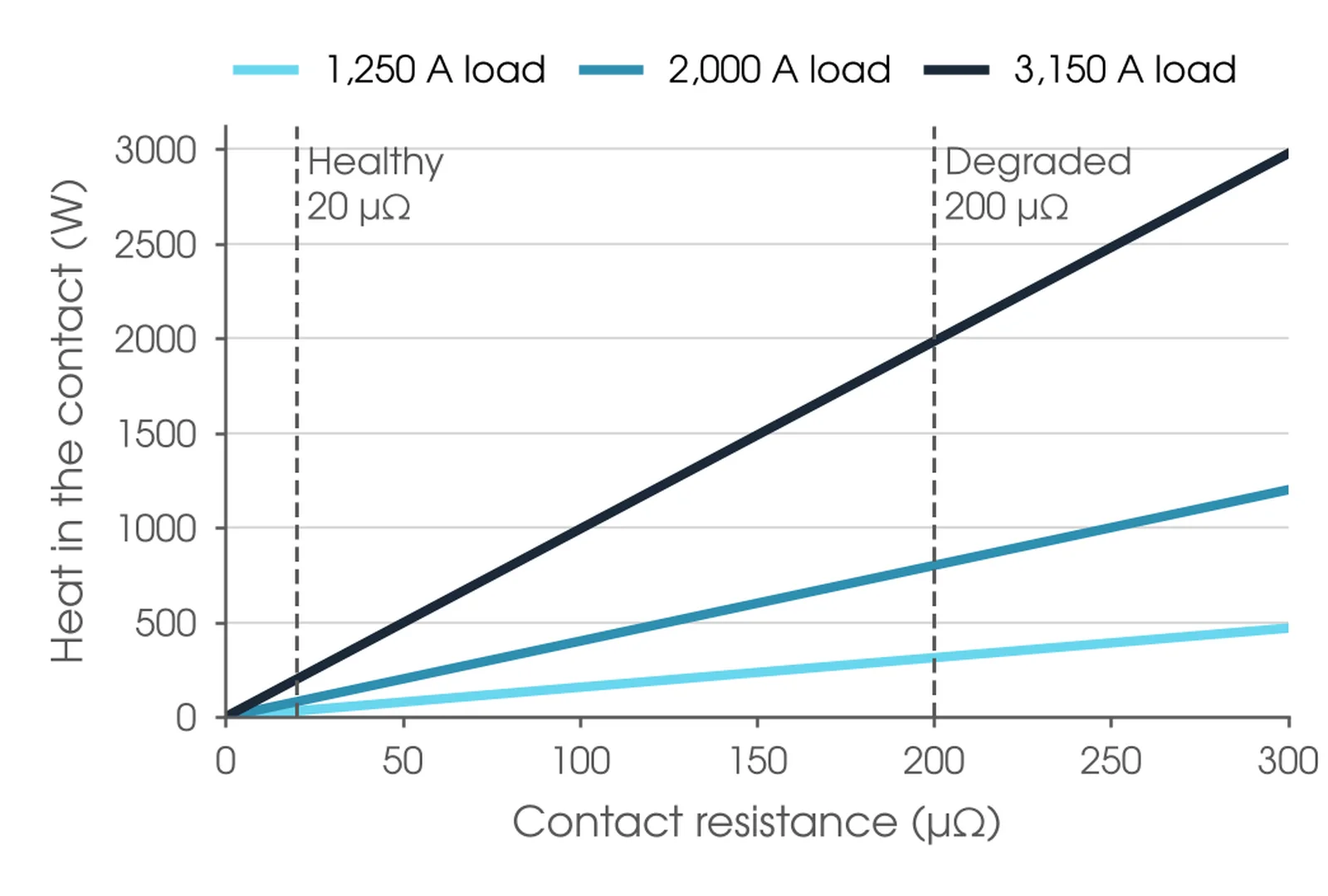
A ductor test finds a contact or joint that is turning into a heat source before the plant is energised. Power lost in a connection is P = I²R. At 2,000 A, a healthy 20 µΩ joint dissipates 80 W; at 200 µΩ the same joint dissipates 800 W, concentrated in a few square centimetres of metal.
The problem feeds itself. Heat accelerates oxidation, oxidation raises resistance and higher resistance produces more heat. Left alone, the cycle ends in a failed joint or contact. Insulation resistance testing does not see it, and thermal imaging only sees it once the plant is carrying load. A ductor test finds it on de-energised plant, at commissioning or during an outage.
When should a ductor test be done?
At commissioning, to set a baseline at a recorded current and temperature; in routine maintenance at the asset owner's interval, so the result can be trended; after any work on contacts or joints; and after events such as heavy fault interruption. The factory routine test result on the manufacturer's certificate is the first point on that record.

Where is ductor testing used?
Any current-carrying connection on HV and LV plant can be ductor tested. The items below are the common ones, with what a high reading usually points to and the test current to use.
| Item | What a high reading points to | Test current |
|---|---|---|
| Circuit breaker main contacts | Pitting, erosion, low contact pressure, misalignment or contamination | 100 A or more |
| Disconnectors and earth switches | Blade misalignment, corroded jaws, weak contact springs | 100 A or more |
| Busbar, switchboard and GIS joints | Loose, over-tightened or contaminated joints | 10 A on small joints; 100 A or more on main busbars |
| Cable lugs, crimps and joints | Under-crimped lug, wrong die, strands not fully inserted | 10 A to 100 A |
| Earth bonds | Loose or corroded bonds, failed exothermic welds | Up to 10 A |
| Battery intercell connectors | Loose or corroded links, measured on a live battery | To the instrument maker's method |
What test current should a ductor test use?
AS 62271.1:2019, clause 7.4.4.1, allows DC at any convenient value from 50 A up to the rated continuous current, or at rated current where that is 50 A or less, and AS/NZS 62271.100:2026 calls it up for circuit breakers. IEEE C37.09-2018, clause 5.14, requires at least 100 A DC, with the result not to exceed the manufacturer's limit. The US Bureau of Reclamation's FIST 3-16 also sets a minimum of 100 A for breaker contact resistance. Our recommendation is 100 A DC on circuit breakers where the equipment and method allow, within the standard's range and the manufacturer's instructions, and 10 A or less on small joints, bonds and conductors. Resolve any conflict between the asset owner's specification and the standards before testing.
Lower current is not always the safer choice. Oxide or contamination films can make a low-current reading high and unstable, and higher current is closer to service conditions and gives a steadier result. The reverse also applies: high current can break through contamination and give a good number on an unhealthy contact. If a 10 A reading is markedly higher than a 100 A reading, treat the difference as a finding. Record the test current with every result and repeat future tests at the same current for reliable trending, recording any change.
How does a ductor test work?
A ductor test is a four-wire, or Kelvin, measurement. One pair of leads drives the test current through the item and a second pair measures the voltage across it. The voltage leads carry almost no current, so lead and clamp resistance drops out of the result.
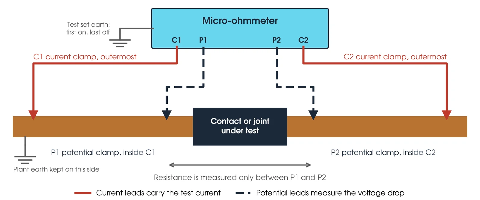
Two rules follow from that. The current clamps, C1 and C2, go furthest from the item under test. The potential clamps, P1 and P2, sit between the current clamps and the item, so only the intended path is measured. Clamp onto bare metal, not paint or oxide, and record the clamp positions so the next test measures the same length. Lead length does not add to a four-wire reading, though long current leads can limit the current the set will drive. Potential clamp position does change the reading.
What is the difference between a ductor test and a megger test?
They measure opposite things. A Megger test, meaning an insulation resistance test, checks that insulation keeps current where it belongs, and a healthy result is a very high resistance. A ductor test checks that a conductor, contact or joint carries current freely, and a healthy result is a very low resistance in micro-ohms. A two-wire meter cannot do the ductor test either: it measures its own leads and clamps, which are in milliohms and can be a hundred times a healthy 30 µΩ contact.
Transformer winding resistance uses the same four-wire principle, but the winding is highly inductive and needs its own method and instrument settings.
How do I set up a ductor test safely?
The ductor test itself is low voltage, but it is run on HV plant inside an access permit, and the hazards come from the plant and its surroundings. Four steps come before any lead is connected:
- Confirm the access permit covers the test, including any temporary removal of earths. Permit earths are removed and replaced only by the person the asset owner authorises.
- Confirm at the plant, with the permit issuer, that it is isolated, proved dead and earthed.
- Barricade and sign every point that will carry test current or could be reached during the test.
- Connect the test set to the station earth before any other lead, and remove it last.
With the conventional method one side of the breaker loses its earth and can pick up induced voltage from adjacent circuits, so keep the earth on the side with the greatest induction risk. If both sides stay earthed, a conventional micro-ohmmeter measures the contact in parallel with the earth loop and reads low; use a method designed for it, such as OMICRON's grounded contact resistance method on CIBANO 500. DC through bushing or ring CTs magnetises the core, and a current step or ripple can look like a fault to connected protection, so short the secondaries at the approved terminals before isolating protection, keep the secondary earth, and use smoothed or ramped DC.
The test is for competent, authorised testing personnel working under the asset owner's safety rules. At Megavar that means assessed testers, with less experienced staff working under direct supervision.
Where do the clamps go on a circuit breaker?
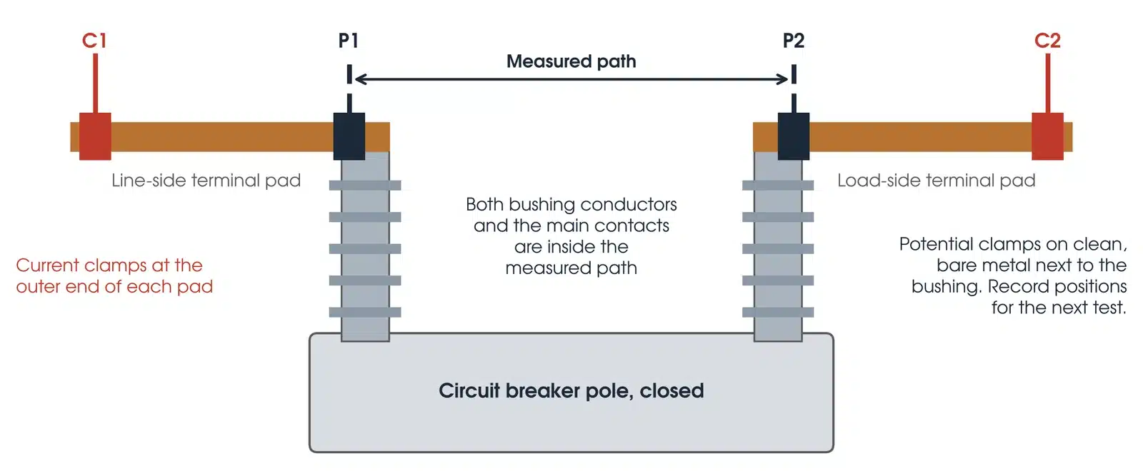
Test one pole at a time. The current clamps go at the outer end of each terminal pad, and the potential clamps go on clean, bare metal next to the bushings, so both bushing conductors and the main contacts sit inside the measured path. Record the positions for the next test.
This guide describes general practice for competent HV testing personnel. It is not a work procedure. Work under the asset owner's safety rules, the access permit and a site-specific safe work method statement. Manufacturer and asset owner criteria take precedence over the general guidance here.
How do I make the measurement?

- Close and confirm. Close the breaker or switch under its operating procedure and confirm it is mechanically closed.
- Connect. Clean clamp points to bare metal without damaging plating. Current clamps outside, potential clamps inside, one pole at a time.
- Inject and settle. Apply the test current and wait for the reading to settle. Inductive paths take longer.
- Forward and reverse. Average forward and reverse readings to cancel thermoelectric voltage at dissimilar metals.
- Record. Resistance, test current, temperature, clamp positions, instrument serial number and calibration date.
- Discharge. On inductive paths, let the instrument finish its discharge before touching a lead. Never break the circuit while current flows.
- Restore. Remove leads, then the test set earth last. Demagnetise affected CT cores, then restore earths and secondary circuits under the permit.
Clean plated contact surfaces with a non-abrasive pad so the plating is not removed.
What are the common ductor testing mistakes?
| Mistake | What it does to the result |
|---|---|
| Potential clamps outside the current clamps | Clamp contact resistance is added to the reading |
| Clamping on paint or oxide | High or unstable reading, or the instrument will not start |
| Breaker tested below the specified current | Below 100 A it is under the IEEE C37.09-2018, clause 5.14, production test current, though AS 62271.1:2019, clause 7.4.4.1, allows 50 A or more. Follow the specified standard, manufacturer and owner |
| Test current not recorded | Reliable trending against the next test is lost |
| No temperature correction | Normal temperature change is read as deterioration |
| Conventional set with both sides earthed | The earth loop is measured in parallel and the reading is falsely low |
| Injecting through in-service CTs | Risk of protection operation and an unplanned trip |
How do I read a ductor test result?
A ductor reading is judged four ways: against the manufacturer's limit, against the asset owner's criterion, against the other poles of the same breaker, and against the item's own history. A pole can pass the limit and still need attention.

What is the acceptable value of contact resistance?
There is no single acceptable value; the limit comes from the equipment and the asset owner. OMICRON gives 10 to 100 µΩ as typical for HV switchgear main contacts. The manufacturer's limit is in the O&M manual or the factory certificate, and USBR FIST 3-16 calls for further investigation when it is exceeded, which may mean opening the breaker to inspect the contacts. For the factory routine test, AS 62271.1:2019, clause 8.4, allows not more than 1.2 Ru, where Ru is the type-tested unit's value. Asset owners set their own criteria: for example, TasNetworks' testing specification for underground developments sets less than 300 µΩ for HV and LV switchgear.
Between poles, NETA guidance, as reported by Schneider Electric, suggests investigating any pole more than 50% above the lowest pole; NETA does not present it as pass or fail. USBR FIST 3-16, clause 2.4, applies the same 50% test to power circuit breakers where no manufacturer limit or factory data exists. Over time, compare with previous results at the same current, corrected to the same temperature. A steady rise is the warning.
What does a bad ductor test result look like?
| Pattern | What it usually means |
|---|---|
| One pole far above the others | A problem at that contact or joint. Recheck clamps and repeat; if it holds, inspect and repair |
| All poles higher than last time | First check current, temperature and clamp positions match the last test |
| Reading will not settle | Loose or dirty clamp, induced current, or an inductive path still stabilising |
| Reading lower than expected | A parallel path, commonly an earth loop with both sides earthed |
| 10 A reading much higher than 100 A | Possible contamination that high current breaks through. Treat it as a finding |
Is my result OK?
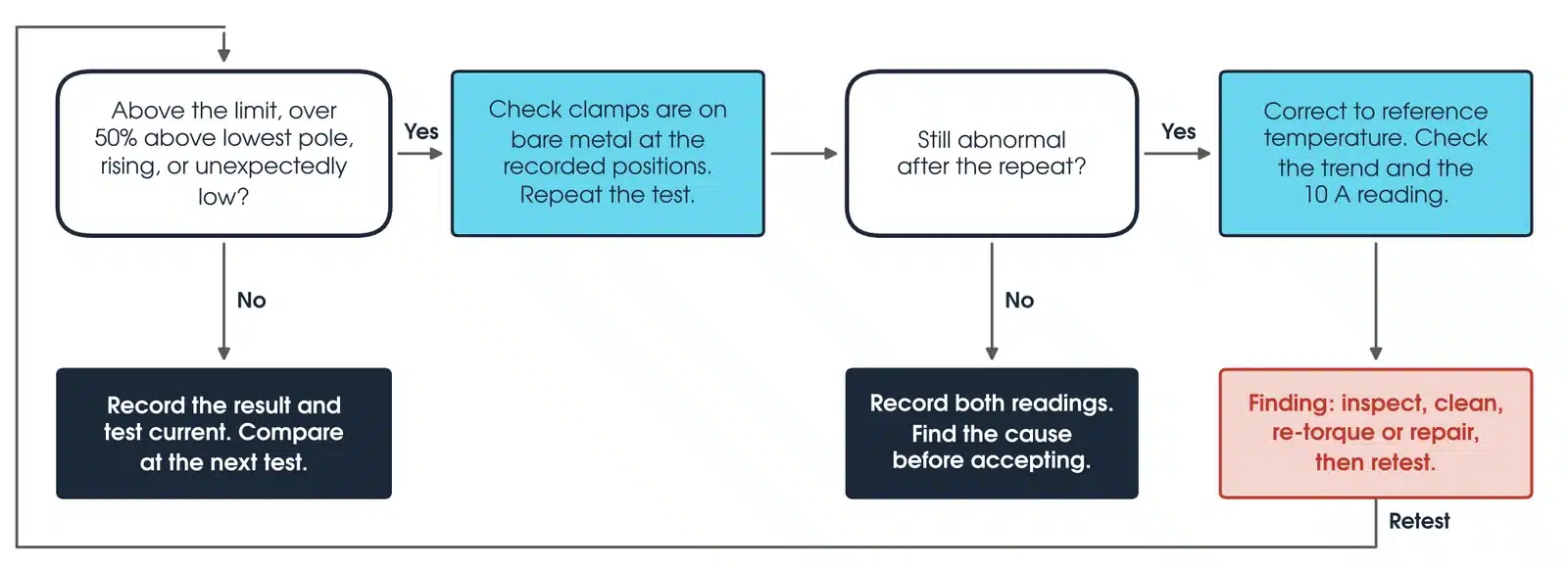
If the reading is above the limit, more than 50% above the lowest pole, rising, or unexpectedly low, check that the clamps are on bare metal at the recorded positions and repeat the test. If the repeat reads normally, record both readings and find the cause of the change before accepting the result. If it is still abnormal, correct it to the reference temperature, check the trend and the 10 A reading, and report it as a finding to inspect, clean, re-torque or repair and then retest.
How do I correct a ductor reading for temperature?
Compare readings at similar temperatures. For copper or aluminium conductors, IEEE Std C57.12.90-2021, clause 5.2, gives the correction as R2 = R1 × (Tk + T2) / (Tk + T1), where R1 is measured at T1 (°C), R2 is the value at the reference temperature T2, and Tk is 234.5 °C for copper or 225 °C for aluminium. Apply it to assembled contacts only where the manufacturer accepts it.
Worked example: a copper conductor reads 50.0 µΩ at 15 °C. At 35 °C it would read 50.0 × 269.5 / 249.5 = 54.0 µΩ. That 8% rise is temperature alone.
What should a ductor test report include?
For each pole or joint, the measured resistance, test current, temperature, and any correction applied with its basis; the manufacturer's limit or asset owner criterion it was judged against; the pole-to-pole spread and the change since the last test; and the instrument model, serial number and calibration date, with the clamp positions used.
What about dynamic resistance testing?
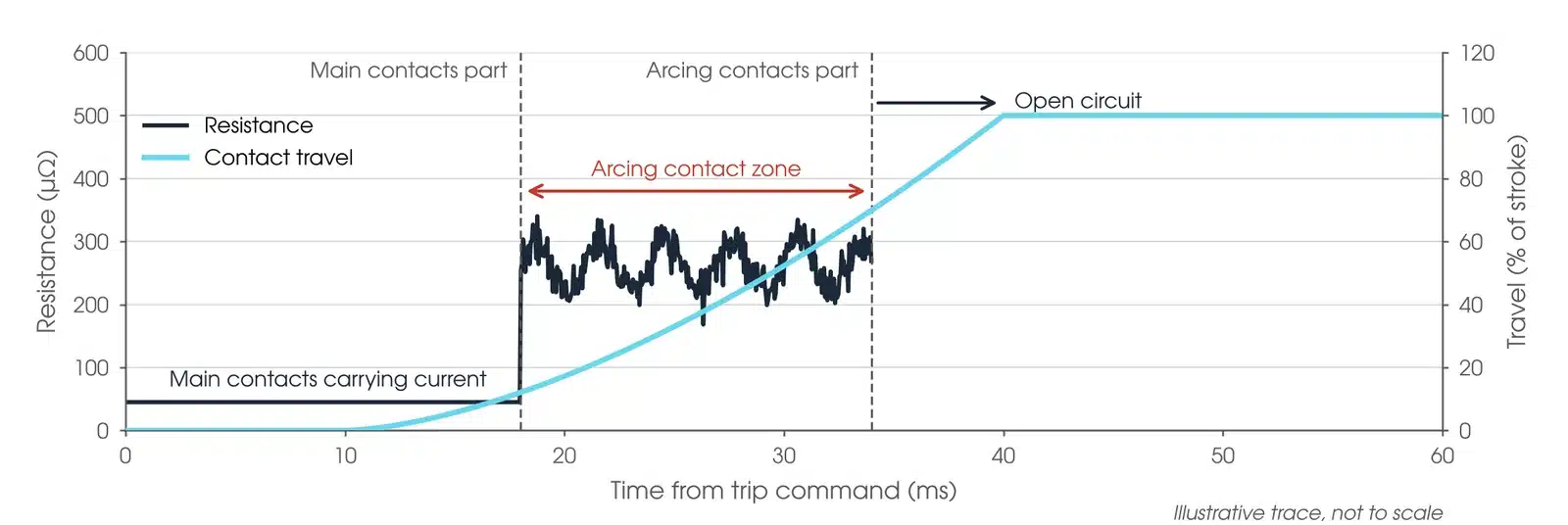
The routine ductor test is static: it measures the main contacts of a closed breaker. Dynamic resistance measurement (DRM) records resistance, current and contact travel while the breaker opens, revealing the arcing contacts in SF6 puffer interrupters that a static test cannot reach. It is typically run at 100 A DC or more.
DRM is a specialist diagnostic. The measurement is fast, and lead and stray reactance affect it, so it is run with a circuit breaker analyser alongside timing and travel tests. Compare a trace with the same breaker's earlier traces or a sister unit, not with a single number.
Which ductor tester should I use?
Match the instrument to the current the item needs. Every instrument below is available calibrated, with leads, from Megavar.
| Instrument | Test current | Best used for |
|---|---|---|
| Megger DLRO 10A | 10 A | Joints, bonds, conductors and small connections; compact and lightweight |
| Megger DLRO 100EB | 100 A | Breakers, disconnectors and busbar joints; battery powered |
| Megger MOM3 Handheld | 300 A | Breaker contacts where a light, handheld high current set is needed |
| Megger DLRO 600A | 600 A | Large breakers and high current paths |
| OMICRON CIBANO 500 | 200 A DC | Contact resistance with timing, coil and motor tests; grounded contact resistance method with both sides earthed |
| OMICRON CPC 100 | 400 A DC | Contact and winding resistance in a multi-function primary test set |
Every instrument is available from Hobart, Launceston, Adelaide and Newcastle through Megavar's micro-ohmmeter and ductor testing equipment hire. If you would rather have the test done, Megavar's engineers carry out circuit breaker testing, substation maintenance and substation commissioning across Australia.
Download the ductor testing guide (PDF)
Frequently Asked Questions
What is a ductor test?
A four-wire micro-ohm measurement of a contact, joint or bond, named after the early Ducter instruments. It is the same test as a contact resistance or DLRO test.
What is a typical result for an HV circuit breaker?
OMICRON gives 10 to 100 µΩ for HV switchgear main contacts. Judge each breaker against its manufacturer's limit and the asset owner's criterion.
Why do two instruments read differently?
Different test current, clamp positions or temperature, or instrument accuracy. A typical specification is ±0.2% of reading plus 2 digits.
Can I test with both sides earthed?
Not with a conventional micro-ohmmeter; use a method designed for it, such as OMICRON's grounded contact resistance method.
Will the test affect CTs and protection?
It can. DC magnetises CT cores, and a current step can look like a fault. Short the secondaries before isolating protection, keep the secondary earth, use smoothed or ramped DC and demagnetise afterwards.
How often should contacts be tested?
At commissioning for a baseline, then at the asset owner's maintenance interval, after work on contacts or joints, and after heavy fault interruption.
Is a continuity tester good enough?
No. A typical continuity tester resolves to 0.01 Ω, which is ten thousand micro-ohms. It cannot tell a good contact from a degraded one.
Does Megavar test as well as hire?
Yes. Our engineers test, commission and maintain HV plant across Australia. Call 1300 730 499.
Need a ductor test done, or the instrument to do it?
Megavar tests circuit breakers and substation plant across Australia, and hires every micro-ohmmeter in this guide. Call 1300 730 499 or email service@megavar.com.au.