Battery testing shows whether a stationary standby battery can carry its DC load when the AC supply fails. The core test is a discharge, or capacity, test: the battery is discharged at a constant current or power to a set end voltage and timed, and the time, corrected for temperature, gives the capacity as a percentage of the manufacturer's rating. Inspections, cell voltages, internal ohmic values and connection resistance fill the gaps between capacity tests. This guide covers vented and valve-regulated (VRLA) lead-acid batteries in substations and plant DC systems: the test types, set-up, safety and how to judge the result.
Download the battery testing guide (PDF)

How can I test if a battery is good?
Run a discharge test. It is the only test that measures the capacity actually there. In a substation the battery's main job is to trip breakers and clear a fault when the AC supply is lost, then close breakers to restore supply (as summarised by Battcon, 2012). If it cannot, protection fails when it is needed.
Float voltage does not answer the question. It shows the charger is working and the cell is charged, not that it has full capacity (as summarised by Megger, 2021). Capacity also changes little for most of a battery's life and then falls quickly: IEEE Std 1188-2025 calls 80% the knee of the curve (Clause 7). Heat speeds it up: VRLA life falls by about one half for every 8 °C above 25 °C (IEEE 1188-2025, Annex B.3, informative).
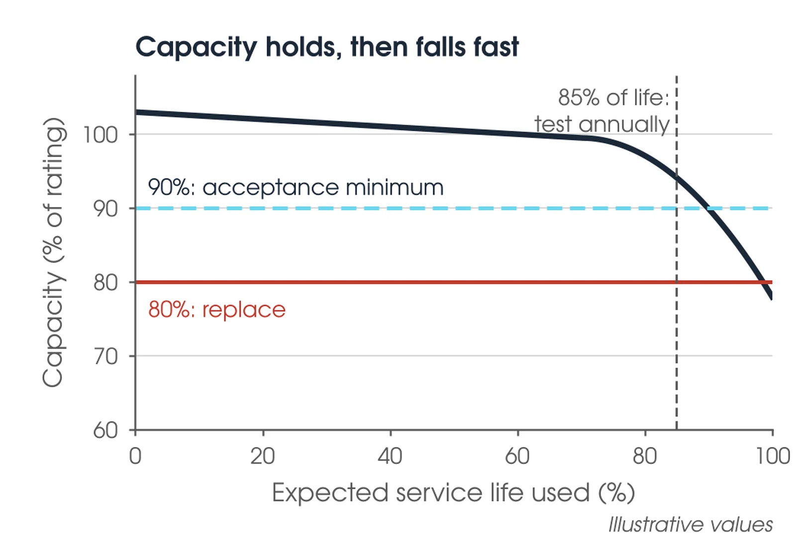
When should a substation battery be tested?
At acceptance, at the factory or on installation, to prove capacity and set the baseline (IEEE 450-2020, 6.2). A performance test within the first two years of service for vented batteries, or within one year for VRLA not acceptance tested on site (IEEE 1188, 5.3.1), then at intervals no longer than 25% of the expected service life. Annually once the battery shows degradation or reaches 85% of its expected service life (IEEE 450, 6.3; IEEE 1188, 5.3.1). Inspections run monthly, quarterly and yearly in between, and a special inspection follows any abnormal event such as a deep discharge or high temperature (IEEE 450, 5.2.5; IEEE 1188, 4.2.5).

What are the three basic battery tests?
For a stationary substation battery, the three tests that matter are the inspection measurements (float voltage, float current and cell voltages), internal ohmic values of each cell, and the capacity (discharge) test. Connection resistance is the fourth check that ties them together. The table shows what each item points to when the result is bad.
| Item | What a bad result points to | Test and interval |
|---|---|---|
| Vented lead-acid battery | Positive grid corrosion, sulphation, sediment build-up (Megger) | Capacity test on cycle; inspections monthly to yearly (IEEE 450, 5.2) |
| VRLA battery | Dryout and negative plate failure, which VRLA usually fails by first (IEEE 1188, 5.3.1) | Capacity test on cycle; ohmic values quarterly (IEEE 1188, 4.2.3) |
| Individual cells or units | Weak cell, short or open cell | Cell voltages; internal ohmic values |
| Intercell and terminal connections | Loose, corroded or poorly made connections | Connection resistance yearly (IEEE 450, 5.2.4) |
| Charger and float | Float voltage out of range, rising float current | Monthly (IEEE 450, 5.2.2) |
| DC system insulation to earth | An earth fault on an unearthed DC system | Earth fault detection and location (USBR FIST 3-6) |
Which discharge test should I use?
There are four. An acceptance test proves capacity at the factory or on installation and sets the baseline for trending (IEEE 450, 6.2; IEEE 1188, 5.2). A performance test measures capacity in service, at about the duty cycle duration (IEEE 450, 6.3 and 7.3). A service test checks the battery as found against its actual duty cycle, with no temperature or age correction (IEEE 450, 7.6). A modified performance test proves capacity and duty cycle in one test, using a constant current raised to bound the duty cycle peaks (IEEE 450, 6.5 and Annex I).
Our recommendation is a performance or modified performance test on the asset owner's cycle, with inspections, ohmic values and connection resistance between tests. The asset owner's specification governs. The chemistry sets the standard: IEEE 450-2020 covers vented lead-acid and IEEE 1188-2025 covers VRLA, and their intervals, inspections and float behaviour differ, so confirm the chemistry before applying any number from either. Nickel-cadmium batteries (IEEE 1106) and grid-scale lithium battery energy storage are outside this guide.
What is a discharging battery?
A discharging battery is delivering current to a load, so its voltage falls as its stored charge is used. A discharge test does that under control. The charger is disconnected and a load bank draws a constant current or power until the battery voltage falls to the design minimum volts per cell times the number of cells (IEEE 450, 7.5). For 60 cells with a design minimum of 1.75 V per cell, the end voltage is 60 x 1.75 = 105 V.
Capacity is the actual time to the end voltage over the rated time, corrected for temperature (IEEE 450, 7.4.2). A capacity test does not prove short high-rate duty: demonstrate the duty cycle with a service or modified performance test (IEEE 450, 7.3). Each cell is read between like-polarity posts of adjacent cells, so the intercell connector drop is included (IEEE 450, 7.5). If the charger cannot be disconnected, the load is increased to make up the current it supplies.
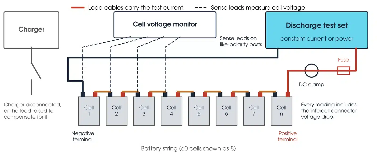
Load test leads must be clean, long enough to avoid accidental arcing and fitted with short-circuit protection (IEEE 450, 4.2). Size the load cables before test day: one load bank maker suggests no more than 3.0 V drop between the battery and the load bank (as summarised by Battcon, 2016).
How do I set up a battery discharge test safely?
A battery cannot be switched off, so the hazards are present for the whole test. Work under the asset owner's safety rules and the access permit, with personnel trained and qualified to work on batteries (IEEE 450, Clause 4).
- Complete a job hazard analysis before any work on the battery (IEEE 450, 4.2).
- Isolate the battery from critical loads and other batteries so a failure cannot affect them (IEEE 450, 7.2). Where the site cannot be without DC, connect a temporary battery first (USBR FIST 3-6).
- Wear shock PPE above 100 V dc and arc flash PPE above 150 V dc (IEEE 1188, 3.2).
- Check the battery room ventilation is running and the exit is unobstructed (IEEE 450, 4.2).
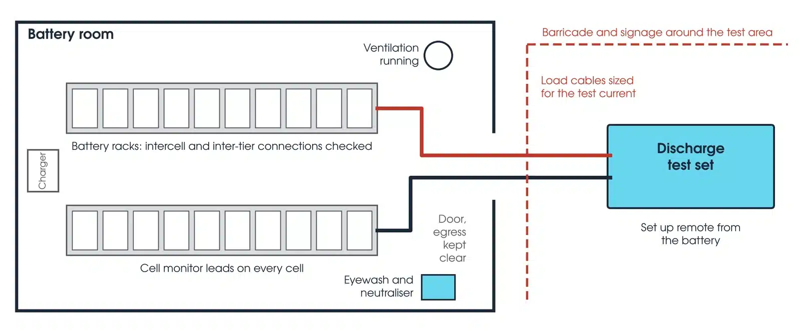
Remove jewellery and use insulated tools; above 1,000 W of short-circuit power, wear thermal hand protection (IEEE 1188, 3.4). Disconnecting a battery does not establish an electrically safe work condition (IEEE 1188, 3.5). Keep naked flames away, and have eyewash, rinse water and bicarbonate of soda solution, 100 g to 1 L of water, on hand (IEEE 450, 4.1 and 4.2). Never place ohmmeter probes across a cell (IEEE 1188, Annex D).
This guide describes general practice for competent testing personnel. It is not a work procedure. Work under the asset owner's safety rules, the access permit and a site-specific safe work method statement. Manufacturer and asset owner criteria take precedence over the general guidance here.
How do I run a battery discharge test?

- Inspect and baseline. Complete the inspections and check every connection resistance (IEEE 450, 6.2 and 7.2). Equalise only if the manufacturer recommends it.
- Record float data. Float current, each cell's float voltage, terminal voltage and the temperature of 10% or more of the cells (IEEE 450, 7.2).
- Isolate and connect. Disconnect the charger, connect the load and the cell monitor.
- Discharge at the set rate. Start timing and hold the rate constant (IEEE 450, 7.5).
- Read cells. Cell voltages, current and terminal voltage at the start, at intervals and at the end: at least three sets (IEEE 450, 7.5), five for VRLA (IEEE 1188, 6.6).
- Manage weak cells. If a cell nears reversal early in the test, stop, bypass it and set a new end voltage for the remaining cells. Allow one downtime only, no more than 10% of the test or 6 min, whichever is shorter, and do not count it as test time. Never bypass during the duty cycle portion of a modified performance test (IEEE 450, 6.5 and 7.5; IEEE 1188, 6.6).
- Stop at the end voltage. Run to the battery end voltage, then record every cell.
- Recharge and restore. Disconnect the test equipment, recharge and return to service (IEEE 450, 7.7).
Scan the connectors with a thermal imager during the discharge (IEEE 1188, 6.1).
What are the common battery discharge test mistakes?
| Mistake | What it does to the result |
|---|---|
| Stopping at 100% of rated time | The true capacity is never measured, so degradation is not seen until it falls below 100% (as summarised by Battcon, 2016) |
| Stopping when the first cell reaches final voltage | The end point is the battery voltage, not one cell (Battcon, 2016) |
| Leaving a failing cell in | An early failing cell left in skews the capacity result (Battcon, 2016) |
| Using the wrong correction table | KT rises with temperature and Kc falls; the wrong table gives a plausible wrong capacity (IEEE 450, Tables 1 and 2) |
| Equalising a VRLA battery by habit | Only if the manufacturer specifically recommends it (IEEE 1188, 6.4) |
| Undersized load cables | The load bank cannot reach the test current (Battcon, 2016) |
How to read a battery test report?
Read three things: the capacity at 25 °C against the acceptance and replacement lines, the change since the last test, and the cell voltages at the end of the test. A battery can be well above the replacement line and still be degrading.
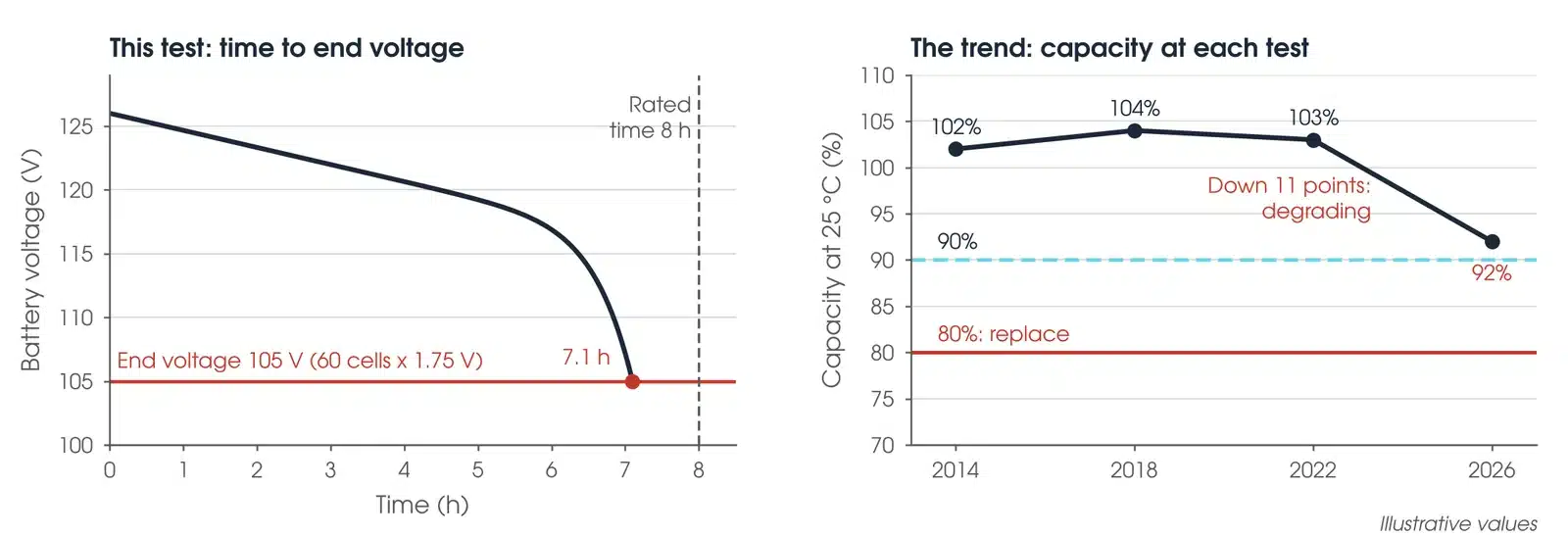
At acceptance, every cell should be at least 90% of rated capacity (IEEE 450, 6.2); for VRLA, at least 90% of rating unless full capacity is specified (IEEE 1188, 5.2). Degradation is capacity more than 10% down on the previous test, or below 90% of rating: from then on, and from 85% of service life, test annually (IEEE 450, 6.3; IEEE 1188, 5.3.1). Replace below 80% of rating (IEEE 1188, Clause 7). For vented batteries IEEE 450 allows up to one year, but replacement at the earliest opportunity where capacity was calculated by the rate-adjusted method (IEEE 450, Clause 8). The asset owner's specification overrides these where it is stricter.
What does a bad battery test result look like?
| Pattern | What it usually means |
|---|---|
| Capacity down since last time | Check the rate, end voltage, temperature and method match the last test, then treat it as degradation |
| One cell far below the rest at the end | A weak cell. Check its ohmic value and connections |
| A cell reverses | An indicator for investigation (IEEE 450, Clause 8) |
| A hot connector | Abnormal intercell connector heating points to a high resistance connection (IEEE 450, 7.5) |
| Service test not met | Replace unless corrective action gives a satisfactory retest (IEEE 450, Clause 8) |
Is my battery capacity result OK?
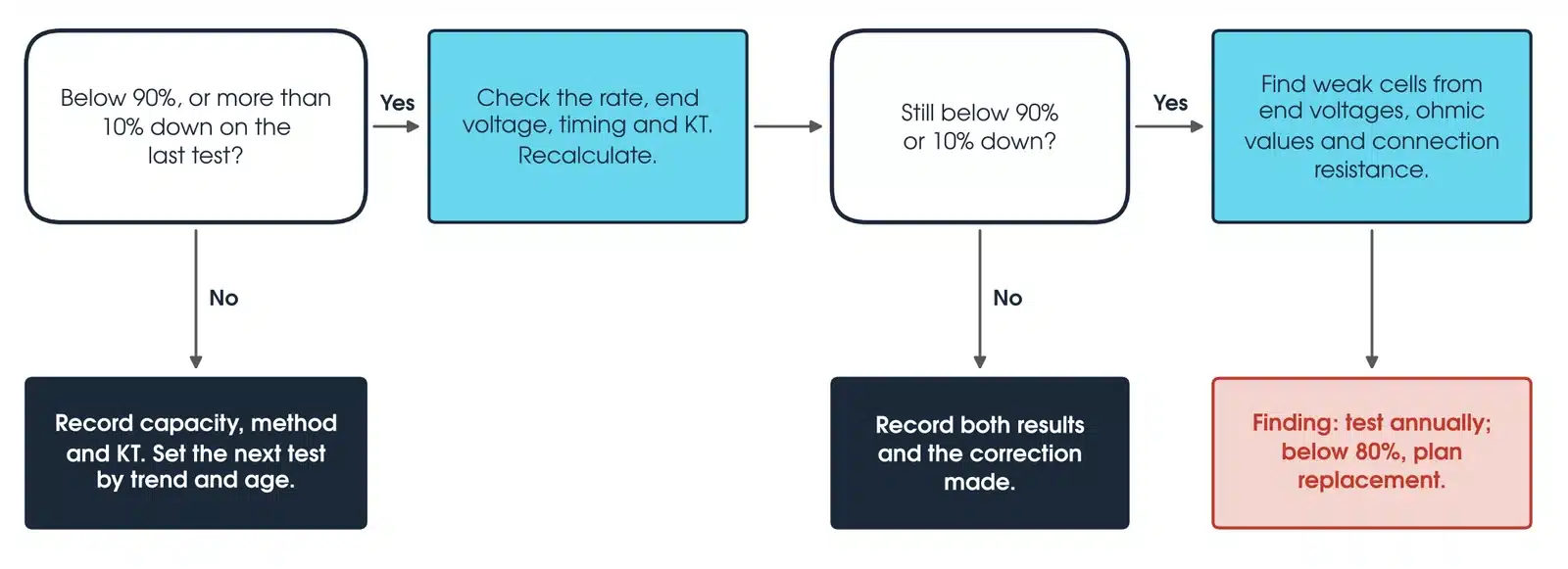
If the capacity is below 90%, or more than 10% down on the last test, check the rate, end voltage, timing and temperature factor, and recalculate. If the recalculated result is normal, record both results and the correction made. If it still holds, find the weak cells from the end voltages, ohmic values and connection resistance, and report it as a finding: test annually, and plan replacement if capacity is below 80%. If the result is normal, set the next test from the capacity trend, chemistry and age: at 85% of expected service life, test annually.
How do I correct battery capacity for temperature?
A cold battery delivers less. For tests over 1 h, correct the time with the factor KT for the cell temperature before the test (IEEE 450, 7.4.2, Equation 1; IEEE 1188, 6.5.2): C = ta / (ts × KT) × 100, where C is capacity at 25 °C (%), ta the actual time to end voltage and ts the rated time. KT is 0.942 at 20 °C, 1.000 at 25 °C and 1.045 at 30 °C (IEEE 450, Table 1). Tests under 1 h use the rate-adjusted method and the factor Kc, which runs the other way. Keep the same method for the life of the battery (IEEE 450, 7.4).
Worked example: a 60-cell battery rated 8 h to 1.75 V per cell reaches 105 V after 7.1 h at 22 °C (KT 0.966). C = 7.1 / (8 × 0.966) × 100 = 91.9%.
What should a battery test report include?
The test type, rate, end voltage, actual time and any bypass downtime; the calculation method, average cell temperature, KT or Kc and the capacity at 25 °C; float voltages before the test, cell voltages at each reading and at the end, and connection resistance; and the change since the last test with the criteria used, on forms that make comparison easy (IEEE 450, Clauses 9 and 10).
How can I test the health of my battery?
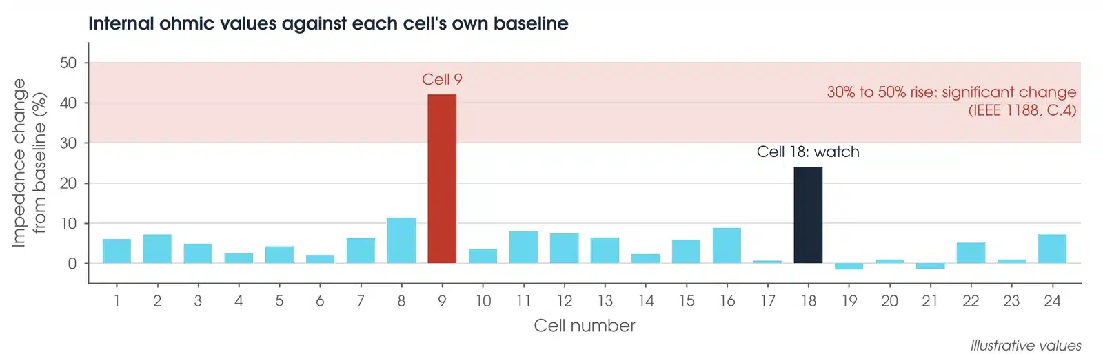
Between capacity tests, measure internal ohmic values, float current and connection resistance. An ohmic test measures the impedance, conductance or resistance of each cell or unit in seconds, with the battery on line. VRLA cells cannot be inspected internally, so ohmic values are the main check between capacity tests (as summarised by EPRI, 2002).
Take the VRLA baseline about six months after installation. An impedance rise of 30% to 50%, or a conductance fall of 23% to 33%, is a significant change (IEEE 1188, C.4). It is a probability, not a capacity: there is no direct correlation between an ohmic reading and capacity, and at a 30% rise the chance a cell is below 80% capacity is about 45% (IEEE 1188, C.4). Monitoring is not a substitute for discharge tests (IEEE 450, 5.2.6).
More than three times normal float current on a VRLA battery can mean dryout or an internal short (IEEE 1188, C.6). Connection resistance more than 20% above the installation value needs re-torque and retest (IEEE 450, 5.3.2), measured post to post in micro-ohms with a micro-ohmmeter (IEEE 1188, Annex D), available through micro-ohmmeter hire.
How are earth faults on a DC system found?
A single earth fault on an unearthed DC system does not trip anything, but a second fault on the other pole can collapse the bus voltage so that relays and trip coils do not work (as summarised by USBR FIST 3-6, section 9). Test equipment can locate a fault with the DC system in service by injecting a small signal between the bus and earth and tracing it with a clamp-on current transformer. USBR investigates any resistance to earth of 500 kΩ or less.
Which battery test equipment should I use?
Use a handheld tester for cell screening and a discharge test set for capacity. Every instrument below is available calibrated from Megavar.
| Instrument | Rating | Best used for |
|---|---|---|
| Hioki BT3554-50 Battery Tester | 6 V and 12 V units, 60 V DC maximum | Internal resistance, voltage and temperature screening of cells and units; handheld |
| Megger Torkel 930 Discharge Test Set | Up to 300 V DC, 220 A | Capacity tests at constant current, power or resistance, with cell voltage monitoring |
| Megger TXL870 Extra Load Unit | Adds up to 112 A, 280 V maximum | Larger batteries where the test current exceeds the Torkel 930 alone |
Every instrument is available with Australia-wide delivery, and BVM cell voltage modules are supplied on request, through Megavar's battery testing equipment hire. If you would rather have the test done, Megavar's engineers carry out battery maintenance and DC system checks as part of substation maintenance across Australia.
Download the battery testing guide (PDF)
Frequently Asked Questions
What is a battery discharge test?
A timed discharge at a constant rate to a set end voltage. The time, corrected for temperature, gives capacity as a percentage of rating.
How often should a substation battery be capacity tested?
Vented within two years of service (IEEE 450, 6.3); VRLA within one year unless acceptance tested on site (IEEE 1188, 5.3.1). Then at no more than 25% of expected life, and annually once degrading or at 85% of life.
Can an impedance tester replace a discharge test?
No. Ohmic values flag weak cells but do not measure capacity (IEEE 1188, C.4).
Can the battery stay on line?
Yes, if the load is raised to make up the charger current (IEEE 450, 7.5). Isolate critical loads first where you can.
Does discharge testing wear out the battery?
Not at the IEEE frequency: at most about six discharges over the life of a vented lead-calcium battery that can deliver 40 or more cycles (as summarised by Battcon, 2012).
What end voltage should I use?
The design minimum per cell times the number of cells. 1.75 V and 1.80 V per cell are common for lead-acid (Megger, 2021).
How are DC earth faults found?
By injecting a small signal and tracing it with a clamp-on sensor, without opening circuits. USBR investigates any resistance to earth of 500 kΩ or less (FIST 3-6, section 9).
Does Megavar test as well as hire?
Yes. Our engineers maintain substation DC systems across Australia. Call 1300 730 499.
Need a battery test done, or the equipment to do it?
Megavar tests and maintains substation DC systems across Australia, and hires every battery test instrument in this guide. Call 1300 730 499 or email service@megavar.com.au.