Cable fault location finds the point where a power cable has failed so that one excavation reaches it. The fault is first diagnosed, then prelocated to a distance along the cable with a reflectometer, then pinpointed on the ground with a surge generator and a receiver that listens for the flashover. This guide covers each method, when to use it, the safety framework around high voltage fault location and how to judge a result.
Download the cable fault location guide (PDF)

How can I locate a cable fault?
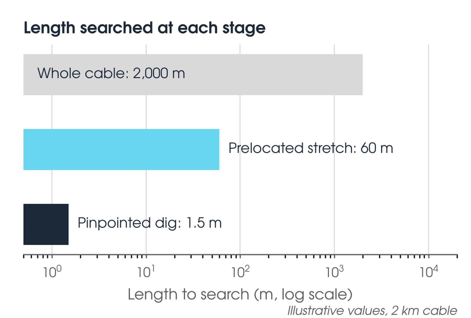
Locate a cable fault in three stages: diagnose it, prelocate it, pinpoint it. Diagnosis measures the fault resistance and decides the method. Prelocation measures the distance to the fault along the cable. Pinpointing finds the spot on the ground. A cable can run for kilometres along a route, so each stage narrows the search: prelocation to a short stretch, pinpointing to a single dig. Every step skipped means more excavation and a longer outage.
Faults vary widely. Megger describes shunt faults from near zero ohms to many megohms, breaks in the conductor, moisture ingress, sheath faults and flashing faults that only break down above a threshold voltage. The fault type decides the method, which is why diagnosis comes first.
The cable will usually go back into service, so the method also limits the stress applied to it. IEEE 400-2023 (clause 5.5) warns that thumping at high voltage can affect the insulation, and asks for the minimum voltage that breaks the fault down.
When is cable fault location needed?
After a cable trips in service, when a cable fails its commissioning or maintenance withstand test, and when a sheath test shows the outer sheath has been damaged. A reference TDR trace taken after laying makes every later fault easier to read, and after repair the cable is retested and a new reference trace taken.

Where is cable fault location used?
On every kind of power cable, from distribution feeders to transmission circuits. The fault type, more than the cable, decides the prelocation method. Megger and High Voltage Inc. both use about 300 Ω as the line between a low resistance fault, which a low voltage TDR can see, and a high resistance fault, which needs a high voltage method.
| Fault type | What it looks like | Prelocation method |
|---|---|---|
| Low resistance shunt fault | Core to core or core to screen, below about 300 Ω (Megger, 2012) | Low voltage TDR: a negative going reflection |
| High resistance shunt fault | Above about 300 Ω; the TDR sees no clear reflection | Arc reflection or impulse current with a surge generator |
| Flashing or intermittent fault | Breaks down only above a threshold voltage, then reseals | Arc reflection, impulse current or voltage decay; condition if unstable |
| Break (series fault) | Conductor open or partly open | TDR: a positive going reflection |
| Moisture ingress | Low insulation resistance over a wet stretch, often all cores | TDR shows a change of impedance over the wet section |
| Sheath (serving) fault | Outer sheath to earth fails its sheath test; core insulation is tested separately | Bridge measurement, then DC or audio frequency pinpointing |
How to find a fault in a cable?
Isolate and earth the cable, find which core has failed, measure the fault, then prelocate and pinpoint it. A multimeter or insulation tester gives the fault resistance between each core, and between each core and the screen; Megger notes an insulation tester may lack resolution below about 5 kΩ, so use the ohms range. A passed test proves little: Megger warns that a 5 kV insulation test will not find a fault that needs 8 kV to break down. Where a fault only shows at higher voltage, each core is raised in turn and the breakdown voltage noted.
IEEE 400-2023 covers field testing of shielded cables rated 5 kV and above and refers fault locating to IEEE 1234 (clause 5.1). Its thumper caution (clause 5.5) and its safety clause (Clause 4) are still relevant to fault location work. The asset owner's rules set who may apply high voltage to their cable, the permit, and the retest required before return to service. Our recommendation: diagnose, TDR every core, use the lowest voltage method that shows the fault, and pinpoint with acoustic and magnetic signals together.
How does a cable fault locator work?
A cable fault locator times reflections. A pulse, or a transient made when the fault flashes over, travels along the cable and part of it reflects wherever the impedance changes. The pulse goes to the change and back, so the distance is L = v × t / 2, where v is the propagation velocity of that cable (Megger, 2012). IEEE 400-2023 (clause 6.5.1) gives the reflection coefficient a range from +1 for an open circuit to −1 for a short circuit, so a break and a short reflect in opposite directions.
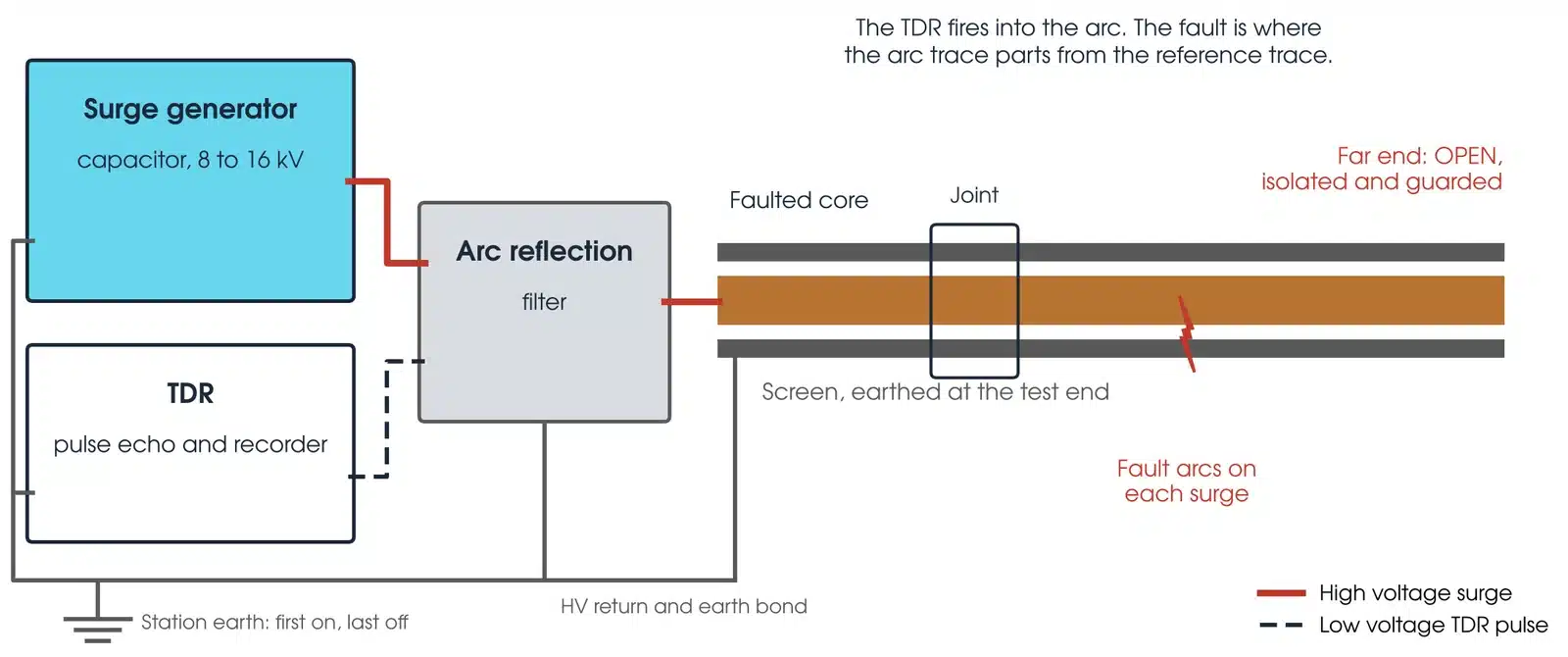
High resistance faults need a high voltage method, because a low voltage pulse passes them by. In arc reflection a reference trace is taken at low voltage, then a surge generator discharges a capacitor into the cable to make the fault arc, and the TDR fires into the arc. The arc is briefly a short circuit, and the fault is where the two traces part (Megger, 2012). In impulse current and voltage decay the surge, or a DC source, breaks the fault down and a coupler records the transient travelling between fault and source. Megger reports voltage decay is used only about 8% of the time, mainly for flashing faults that reseal.
What is a cable fault locator TDR?
A time domain reflectometer, or TDR, sends a low voltage pulse into the cable and shows a reflection at every change of impedance: joints, the cable end, a short or a break. It needs no high voltage, suits low resistance faults and breaks, and gives the reference trace for every later method. IEEE 400-2023 puts a TDR measurement at 5 to 10 minutes once connected (clause 6.5.2), and notes a blind spot near the injection point that depends on the pulse width (Table 12). A TDR is not an insulation test: IEEE 400 notes it most likely will not detect even serious insulation defects.
How do I set up cable fault location safely?
Fault location applies repeated high voltage surges to a cable that runs out of sight. Four steps come before the first surge:
- Work only on a de-energised, isolated cable (IEEE 400-2023, Clause 4), under the asset owner's safety rules with the permit covering both ends.
- Clear and guard the far end, and keep voice contact with it. The cable is at high voltage there too (IEEE 400-2023, Clause 4).
- Disconnect VTs, surge arresters and other items that cannot take the surge, and consider the voltage across any open switch to live plant (IEEE 400-2023, clause 5.4.3).
- Prove dead and apply earths before each connection change. A cable holds charge, and dielectric absorption rebuilds it after a discharge (IEEE 400-2023, Clause 4).
Four hazards are specific to fault location. Stored energy: a portable surge generator such as the Megger MIG16-2 stores 1,500 J at 8 or 16 kV (Megger, 2012), so discharge and earthing sticks must be rated for the voltage and the cable capacitance. The faulted core and its terminations rise to the surge voltage on every pulse, so people and machines keep clear of open pits, exposed terminations and joints. Burning a fault too long can make a dead short to earth that is very hard to pinpoint acoustically (Megger, 2012). And other services along the route are located and marked before any excavation.
The work is for competent HV testing personnel authorised under the asset owner's rules; AS 2067 clause 2.1.1 requires competent personnel for HV testing in substations; on cables between installations the asset owner's rules govern. This guide describes general practice. It is not a work procedure. Work under the asset owner's safety rules, the access permit and a site-specific safe work method statement. Manufacturer and asset owner criteria take precedence over the general guidance here.
How do I make the measurement?

- Isolate and earth. Isolate and earth both ends, disconnect connected plant and guard the far end.
- Identify the faulted cable. Confirm which cable and which core has failed, by continuity or by comparing TDR traces of each core (Megger, 2012).
- Diagnose the fault. Measure resistance core to core and core to screen. Where a fault only shows at higher voltage, raise each core in turn, within the voltage limit the asset owner sets for that cable, and note the breakdown voltage.
- Prelocate. Low resistance faults and breaks with the TDR; high resistance and flashing faults with arc reflection, impulse current or voltage decay.
- Condition if needed. If the fault will not break down steadily, a burn function can lower its resistance. Return to arc reflection once the discharge is stable (Megger, 2012).
- Pinpoint. Walk the prelocated stretch with the surge running at the lowest voltage that flashes the fault over, and mark the spot where sound and magnetic pulse are closest in time.
- Repair and retest. After the repair, retest the cable before it is re-energised (IEEE 400-2023, clause 5.3.3), and take a new TDR reference trace.
Prelocate from both ends on a long cable. BAUR reports prelocation accuracies of up to 0.5% of cable length, depending on the method; measuring from both ends improves accuracy.
How can I locate a fault in an underground cable?
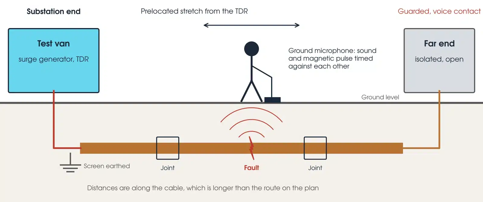
With the same sequence, then by pinpointing on the ground. The as-built records and joint positions turn the prelocated distance into a stretch of route. A surge generator then makes the fault flash over at a steady rate, and the operator walks the stretch with a ground microphone. Each surge makes a bang at the fault and radiates a magnetic pulse that arrives almost at once; the delay between the pulse and the sound is shortest directly over the fault (Megger, 2012), and the change in delay as the operator moves gives direction as well as loudness. Use the lowest surge voltage that still flashes the fault over; on a two range generator such as the Megger MIG16-2 the lower range delivers its full energy at the lower voltage (Megger, 2012). IEEE 400-2023 (clause 5.5) also asks for the minimum voltage, to limit stress on the insulation. High Voltage Inc. puts it plainly: a measure of success is how many excavations there have been.
What are the common cable fault location mistakes?
| Mistake | What it does to the result |
|---|---|
| Skipping the diagnosis | The wrong method is chosen and the fault never shows on the trace |
| Velocity not set | Every distance on the TDR scales with v; a wrong value moves the fault |
| Cable length read as route length | Snaking, slack and joints make the cable longer than the route on the plan |
| First impulse current pulse measured | It includes the ionisation delay; Megger advises using the second or third pulse |
| Surging at maximum voltage | Stresses the healthy insulation for no benefit (IEEE 400-2023, clause 5.5) |
| Burning too long | A dead short to earth is silent to the ground microphone |
| No retest after repair | A second weak spot can fail on re-energisation |
How do I read the result?
A trace is read against something known: the healthy cores, the reference trace, the route records and a calibrated velocity. A reflection that appears on one core and not the others, or on today's trace and not the reference, is the fault.
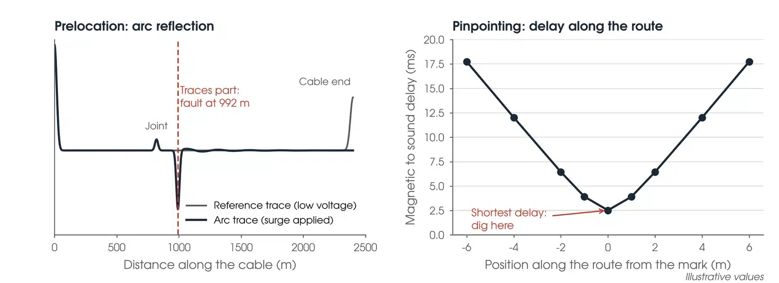
A healthy core on the same cable gives the same joints and end at the same distances, so the difference is the fault. The fingerprint taken after laying shows every joint, so a new reflection stands out. Joint positions and cable lengths from the as-built records turn a distance into a place on the ground. And the velocity is checked on a known length or a known joint before any distance is trusted.
What does a TDR trace tell you?
| Pattern | What it usually means |
|---|---|
| Negative reflection | A drop in impedance: a low resistance shunt fault or a short (IEEE 400-2023, clause 6.5.1) |
| Positive reflection | A rise in impedance: an open circuit or a break in the conductor |
| Reflection at a joint | Joints show on every trace; a fault at a joint shows as a change against the good cores |
| No clear reflection | The fault is high resistance: check the connections, range and velocity first; if there is still nothing, it is likely a high resistance fault for a high voltage method |
| Gradual change over a section | Water in the cable over a length, often reaching to the next joint (Megger, 2012) |
Is my result OK?
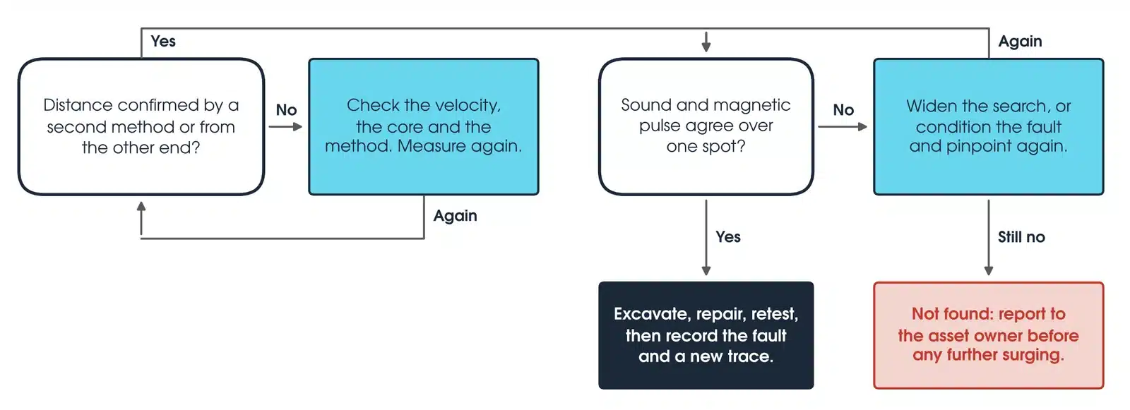
Confirm the prelocated distance before anyone digs: by a second method, or by measuring from the other end. If the two disagree, check the velocity, the core and the method, and measure again. Then confirm that sound and magnetic pulse agree over one spot before excavating. If they do not, widen the search or condition the fault and pinpoint again. If the fault still cannot be found, report to the asset owner before any further surging. Once it is found, excavate, repair, retest, and record the fault and a new reference trace.
How do I calculate the distance to the fault?
Set the velocity from a length you know before reading any distance; the end of a healthy core is the usual reference. v = 2 × L(known) / t(end), and then L(fault) = v × t(fault) / 2, where t is the time to the reflection on the TDR. Worked example, illustrative values: a core of known length 2,400 m reflects its end at 30.0 µs, so v = 2 × 2,400 / 30.0 = 160 m/µs. The fault reflects at 12.4 µs: 160 × 12.4 / 2 = 992 m along the cable.
What should a cable fault location report include?
The cable, route, length and core, with the fault type and resistance found at diagnosis. The prelocation method, the velocity used, the distance from each end, and the saved traces. The surge voltage used and the location marked against fixed references and joint positions. And the test after repair, with its voltage and result (IEEE 400-2023, clause 5.6), and the new reference trace.
What about sheath faults and long cables?
A damaged outer sheath lets water reach the screen and corrode it, and can lead to a core fault later; BAUR notes sheath fault location is gaining importance for this reason. A DC sheath test between the metallic screen and earth, at the voltage the cable maker or asset owner sets, typically 3 to 10 kV to IEC 60229, shows the damage. Megger notes sheath to earth faults pinpoint very reliably with DC or audio frequency methods.
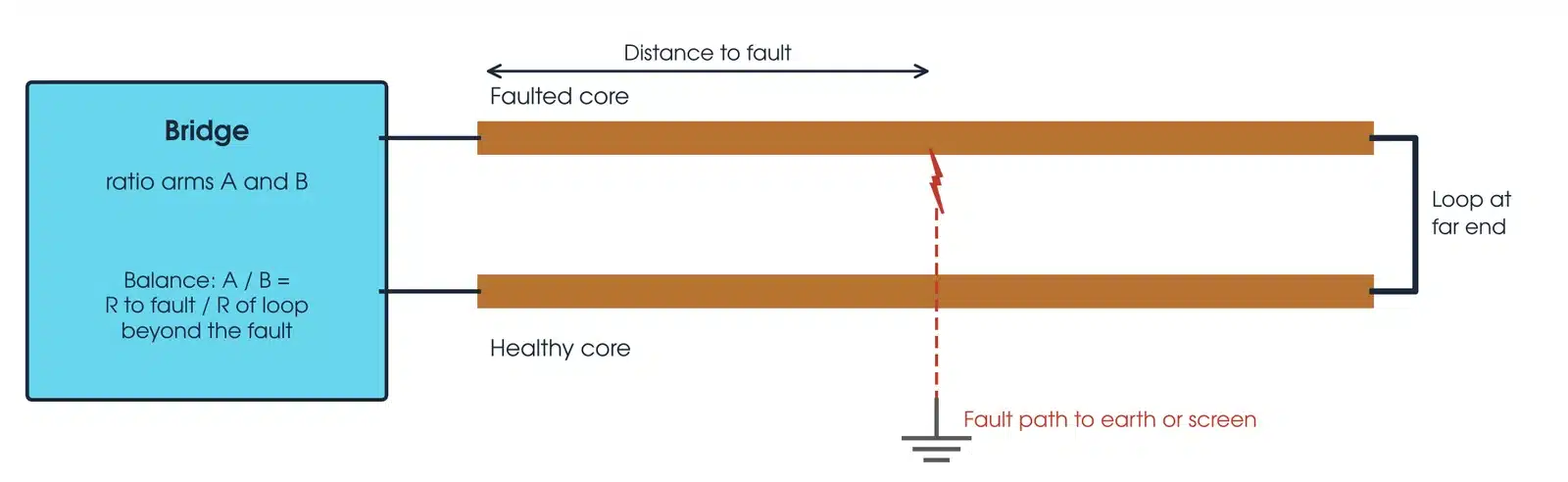
A Murray bridge loops the faulted conductor to a healthy one at the far end and compares resistances. It needs a healthy core, and it does not lose accuracy with distance (BAUR, 2020).
Long cables are harder. TDR sensitivity falls with length and with the number of joints, and a high resistance fault cannot be seen by low voltage TDR; arc reflection, or burning it down, makes it visible (BAUR, 2020). BAUR reports accuracies of up to 0.5% of length, depending on the method, and Murray bridge location of faults on submarine cables hundreds of kilometres long. On long transmission cables BAUR recommends keeping fault location equipment at the cable ends so a fault can be located at once.
Which cable test sets should I use?
Fault location itself is a Megavar testing service. The test sets below diagnose the fault, test the sheath and prove the repair, and are available calibrated, with leads, from Megavar.
| Instrument | Capability | Best used for |
|---|---|---|
| Megger MIT1020 10 kV | Insulation resistance to 10 kV | Fault diagnosis, core and sheath tests |
| Megger MIT520 5 kV | Insulation resistance to 5 kV | Fault diagnosis and sheath tests on distribution cable |
| HVA 60 kV VLF test set | VLF withstand to 60 kV peak (42 kV RMS) | Proving a suspect cable and retesting after repair |
| HVA 28 kV VLF with tan delta | VLF withstand and tan delta | Retest and condition check of the repaired cable |
Every instrument is available from Hobart, Launceston, Adelaide and Newcastle through Megavar's cable testing equipment hire. To have the fault found, Megavar's engineers carry out HV cable testing and fault location on XLPE and paper insulated cables across Australia. The retest after repair is covered in the VLF cable testing guide, the insulation resistance testing guide covers diagnosis by insulation resistance, and the partial discharge testing guide covers finding weak spots before they fail.
Download the cable fault location guide (PDF)
Frequently Asked Questions
How can I locate a cable fault?
Diagnose the fault resistance, prelocate it with a TDR or a high voltage method, then pinpoint it on the ground with a surge generator and an acoustic and magnetic receiver.
How does a cable fault locator work?
It times reflections of a pulse sent along the cable, or of the transient made when a surge breaks the fault down. Distance is velocity times time, halved.
How to find a fault in a cable?
Isolate and earth it, find which core has failed, prelocate the fault to a distance, then walk the route with a receiver while the cable is surged.
What is a cable fault locator TDR?
A time domain reflectometer: it sends a low voltage pulse and shows reflections at every change of impedance along the cable.
How can I locate a fault in an underground cable?
The same sequence. The cable records turn the prelocated distance into a place on the ground, and pinpointing finds the spot to excavate.
Can a thumper damage a cable?
Thumping at high voltage can affect the insulation, so IEEE 400-2023 (clause 5.5) asks for the minimum voltage that breaks the fault down.
Does the cable need testing after repair?
Yes. IEEE 400-2023 recommends retesting after any fault repair (clause 5.3.3).
Does Megavar locate cable faults?
Yes, with TDR and thumper and acoustic methods, as part of its HV cable testing service. Call 1300 730 499.
Need a cable fault found?
Megavar locates cable faults and tests HV cables across Australia, and hires the cable test sets used to prove the repair. Call 1300 730 499 or email service@megavar.com.au.