Circuit breaker testing confirms that a breaker opens and closes on command, fast enough, with its poles together. An analyser times each pole from the coil command to the contact change, records contact travel and coil current, and repeats the operations at reduced control voltage. This guide covers which operations to time, the limits that apply, how to connect the analyser safely and how to judge the result.
Download the circuit breaker testing guide (PDF)

Why measure circuit breaker timing?
A breaker may sit closed for months, then has to clear a fault in a few tens of milliseconds, and the protection settings assume it will. Timing and travel tests show whether the mechanism can still do that. Dried grease, worn latches, tired springs and failing coils slow a breaker long before it fails to operate outright.
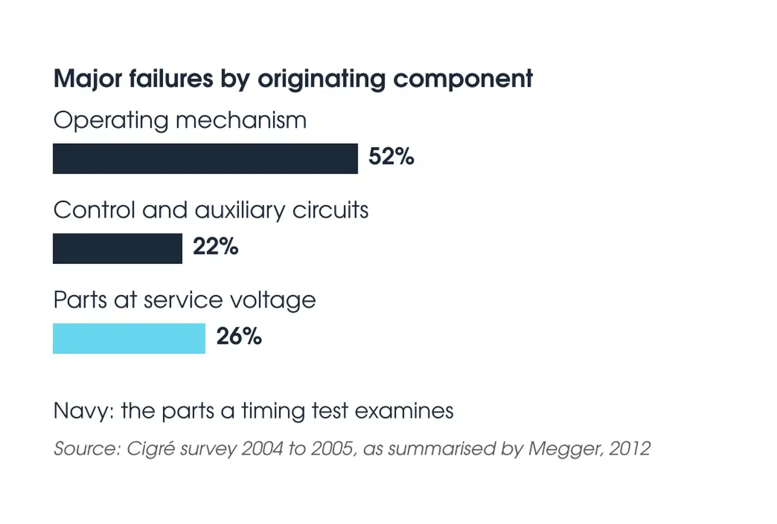
Most failures start in exactly those parts. In the Cigré survey summarised by Megger (2012), the operating mechanism caused 52% of major breaker failures and the control and auxiliary circuits a further 22% (2004 to 2005). A contact resistance test does not examine either; a timing test examines both. The poles must also move together: AS/NZS 62271.100:2026, clause 6.101, limits the spread between poles to 1/6 cycle on opening and 1/4 cycle on closing.
When should a circuit breaker be tested?
At the factory, where the routine test records operating times and the travel curve for every breaker (AS/NZS 62271.100:2026, 8.101); at commissioning, timing every pole and every trip coil as the baseline (11.3.102.2.5.1); at the asset owner's maintenance interval, so the results can be trended; after any adjustment or repair of the mechanism; and after heavy fault duty or a slow operation.

Where is circuit breaker testing used?
Every type of HV and MV circuit breaker is timed. What the test finds, and what to watch for, depends on the interrupter and the mechanism.
| Breaker | What timing and travel find | Points to note |
|---|---|---|
| Live-tank SF6 (HV) | Slow mechanism, pole spread, spread between units in one pole | Time each interrupter unit; 1/8 cycle within a pole on opening (6.101) |
| Dead-tank SF6 (HV) | Slow mechanism, worn damper, pre-insertion resistor timing | Linear transducer is usual (Megger) |
| Vacuum (MV switchboards) | Slow mechanism, contact bounce on closing | The maker defines the travel check (Annex G) |
| Bulk and minimum oil | Dashpot wear, friction in the linkage | Travel and coil current are key (Megger) |
| Independent pole operated | Pole discrepancy, one slow pole mechanism | Coil current on each pole; check pole discrepancy |
| Reclosers | Reclose sequence and dead times | Covered by IEC 62271-111, not AS/NZS 62271.100 |
What is the IEC standard used for circuit breaker testing?
IEC 62271-100 is the circuit breaker standard, adopted in Australia as AS/NZS 62271.100:2026 and read with the common specification AS 62271.1:2019. At commissioning it calls for the opening and closing time of each pole on O, C and the O and C within a CO, the pole spread, a test of every trip coil and a record of the supply voltage (11.3.102.2.5.1). AS 62271.1:2019 sets the release voltages: closing releases operate from 85% to 110% of rated supply, opening releases from 70% (DC) or 85% (AC) to 110% (6.9.2, 6.9.3).
In North American practice, IEEE C37.09-2018 operates the breaker five times closed and five times open at minimum and at maximum control voltage (5.11), requires opening times to be recorded for all breakers (5.12), and lists timing and travel among the tests after erection (Clause 7). Our recommendation is to time O, C, CO and the nameplate operating sequence at rated supply, then repeat O and C at the minimum release voltage. The manufacturer's programme governs.
Which operations should be timed?
Open (O) and close (C) give the opening and closing time of every pole and the spread between poles. Close-open (CO) closes and trips at once and measures CO timing. Trip-free operation and anti-pumping are verified separately with the maker's command sequence; for anti-pumping, a maintained close command must not cause repeated closing (AS/NZS 62271.100:2026, 6.4). O – t – CO is the first reclose of the rated operating sequence, O – t – CO – t' – CO, with t = 0.3 s for rapid auto-reclosing; use the nameplate values of t and t' (5.104). Record the control voltage at the coil on every operation: timing changes with supply voltage, so results at different voltages cannot be compared.
How does a circuit breaker timing test work?
The analyser energises the trip or close coil and starts its clock. Each main contact channel stops at the instant its contact parts or touches. Opening time runs to separation of the arcing contacts in all poles, and closing time to contact touch in all poles (AS/NZS 62271.100:2026, 3.7.131 and 3.7.134). The same operation records coil current, the auxiliary contacts and, with a transducer on the mechanism, contact travel and velocity.
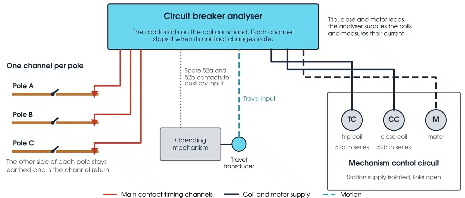
Three connection rules follow. Each pole, or each interrupter unit, gets its own channel so the spread can be read. The coils are driven from the analyser: open the station supply links first, then land the trip, close and common leads (OMICRON). The travel transducer goes on the maker's mounting point, or as near the moving contact as possible, and in the same place every time.
What is the CRM test in VCB?
CRM is contact resistance measurement. On a vacuum circuit breaker (VCB) it is a static micro-ohm test of the closed main contacts, made with separate DC current and voltage leads. It is a different test from timing and is covered in Megavar's ductor testing guide. Dynamic resistance measurement, which reads resistance while the contacts move, applies to SF6 arcing contacts rather than vacuum interrupters (Megger).
How do I set up circuit breaker testing safely?
The breaker will operate during the test, on HV plant inside an access permit. Four steps come before any lead is connected:
- Confirm the access permit covers the test, including operation of the breaker and any temporary removal of earths by the person the asset owner authorises.
- Confirm at the plant, with the permit issuer, that it is isolated, proved dead and earthed.
- Barricade and sign the area. Keep everyone clear of the poles, linkages and mechanism.
- Connect the analyser to the station earth before any other lead, and remove it last.
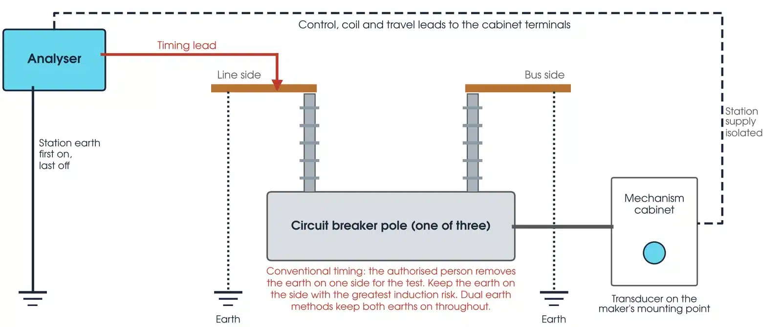
With the conventional method, the open breaker leaves one side unearthed, and coupled current from nearby live plant can reach harmful levels (Megger). Keep the earth on the side with the greatest induction risk (Doble). Dual earth timing methods keep both earths on throughout, such as Megger DualGround, Doble's dual ground option and OMICRON's CIBANO 500 with CB MC2 modules. The mechanism is charged and can operate without warning, and a first trip test is wired into a live control panel on an in-service breaker (USBR FIST 3-16).
This guide describes general practice for competent HV testing personnel. It is not a work procedure. Work under the asset owner's safety rules, the access permit and a site-specific safe work method statement. Manufacturer and asset owner criteria take precedence over the general guidance here.
How do I test an electrical circuit breaker?
Isolate and earth the breaker under a permit, connect an analyser, then time open, close, close-open and reclose operations at rated and at minimum control voltage. The seven steps are:

- Plan and record data. Nameplate, rated control voltage, the maker's timing and travel limits, and the last results.
- Isolate control supply. Open the trip, close and motor supply links before landing any lead (OMICRON).
- Connect channels. One timing channel per pole or unit, the coil leads, a spare auxiliary contact, and supply voltage monitoring.
- Mount the transducer. On the maker's mounting point, with the conversion factor from the maker.
- Time O, C, CO and O-CO. Record the first operation as found, before any exercising, then the full set at rated supply.
- Minimum voltage tests. Repeat O and C at the minimum release voltage, then find the pick-up voltage of each coil.
- Restore. Leave the breaker in the state the permit requires, remove the leads, close the supply links, test set earth last.
Use a test supply that delivers full coil current without sagging (EPRI TR-112783).
What are the common circuit breaker testing mistakes?
| Mistake | What it does to the result |
|---|---|
| Exercising the breaker before the first test | The slow first operation is lost (USBR FIST 3-16) |
| Supply voltage not recorded | Timing and coil current cannot be compared with the next test |
| Loose clamps | Vibration lifts a clamp and shows false bounces (Megger) |
| Transducer moved | Travel and velocity no longer compare with earlier records |
| Low sampling rate | Bounce is missed; Megger recommends at least 10 kHz for timing |
| Coil held on too long | Long pulses overheat coils during pick-up tests (OMICRON) |
| Bypassing control devices | The control scheme is not tested as it works in service (OMICRON) |
How do I read a circuit breaker timing result?
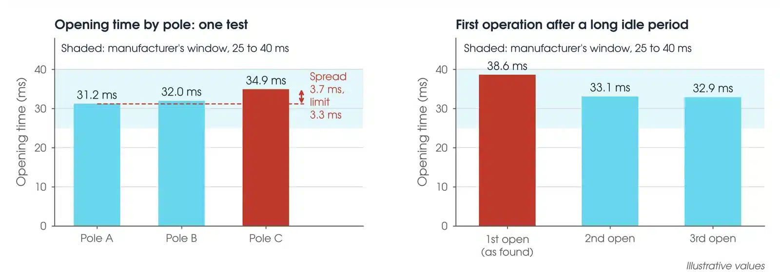
A timing result is judged against the manufacturer's limits, against the standard's pole spread limit, against the travel envelope, and against the breaker's own history. Every pole can be inside the maker's window and the breaker can still fail.
Opening, closing and reclose times, velocity and travel come from the maker (AS/NZS 62271.100:2026, 6.105), and the factory routine test records them on every breaker (8.101). IEEE C37.09-2018 gives no timing limits of its own. For field maintenance, judge travel against the maker's criteria. The Annex G reference envelope (±5% of stroke, or ±2 mm for strokes of 40 mm or less) is the production conformity check, and vacuum and some MV breakers use a maker-defined method. Where the maker gives no limit, trend the value; there should be very little change over time (USBR FIST 3-16).
What pole spread is acceptable?
AS/NZS 62271.100:2026, clause 6.101, allows 1/6 cycle between poles on opening and 1/4 cycle on closing, at rated frequency; series units within one pole are held to 1/8 cycle on opening. At 50 Hz that is 3.3 ms and 5.0 ms. The US Bureau of Reclamation's FIST 3-16 uses 2 ms between phases for most breakers. A maker's tighter value applies where one is given.
What does a bad timing result look like?
| Pattern | What it usually means |
|---|---|
| Opening and closing both slow | Friction through the whole mechanism, such as corrosion in the linkage (Megger) |
| Closing slow, opening normal | Closing system or latch binding (Megger) |
| First operation slow, then normal | Dried or stiff lubricant (USBR FIST 3-16) |
| One pole late | Independent pole: that pole's mechanism. Ganged: the linkage to that pole |
| Bounce or large rebound | Damper wear; rebound brings a risk of restrike (USBR FIST 3-16) |
Is my result OK?
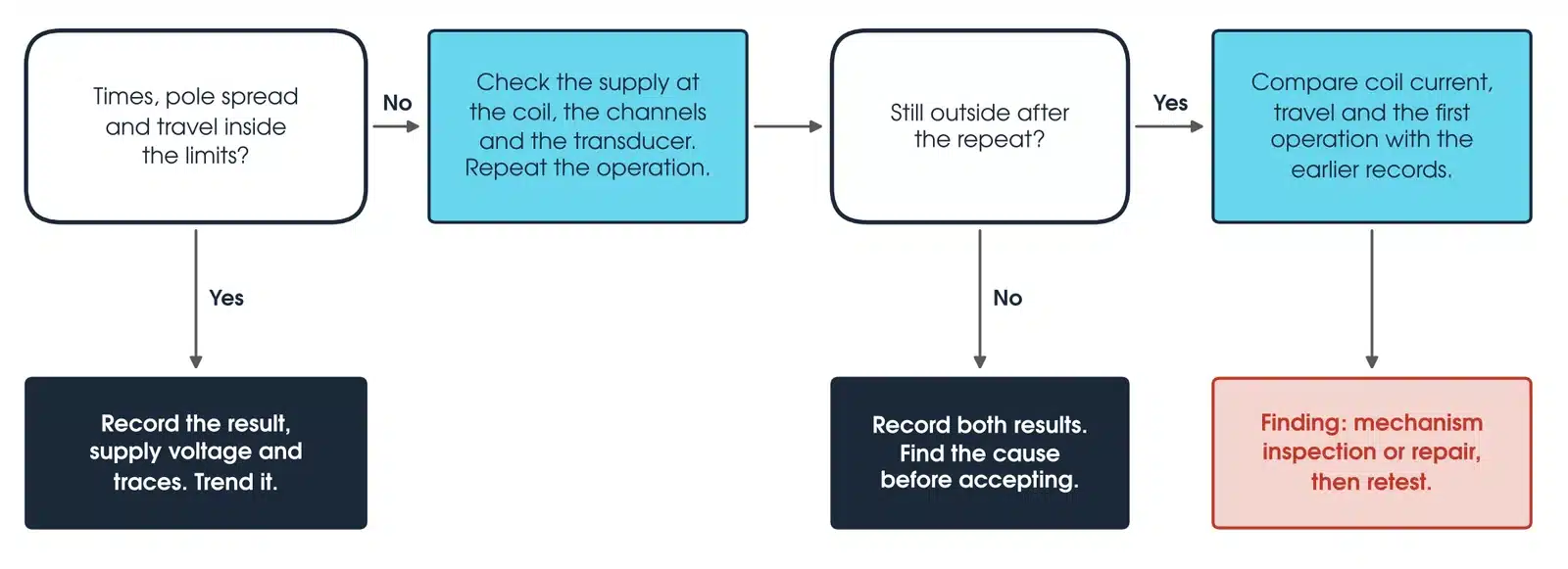
If times, pole spread or travel are outside the limits, check the supply voltage at the coil, the timing channels and the transducer, and repeat the operation. If the repeat is inside the limits, record both results and find the cause before accepting: a slow first operation that improves with exercising is a mechanism finding, not a set-up error. If it is still outside, compare the coil current, the travel curve and the first operation with the earlier records, and report a finding for mechanism inspection or repair, then retest.
How do I work out the pole spread limit?
The limit in clause 6.101 is a fraction of a cycle at rated frequency: limit (ms) = fraction × 1,000 / f. At 50 Hz one cycle is 20 ms, so 1/6 cycle is 3.3 ms on opening and 1/4 cycle is 5.0 ms on closing.
Worked example: opening times of 31.2, 32.0 and 34.9 ms are each inside a 25 to 40 ms window, but the spread is 34.9 minus 31.2, which is 3.7 ms. That exceeds 3.3 ms, so it is a finding.
What should a circuit breaker test report include?
For each operation, the opening and closing time of each pole, the pole spread, travel, velocity and the coil current trace; the conditions, meaning supply voltage at the coil, mechanism pressure, temperature and whether it was the first operation; the criteria used, meaning the maker's limits, the 6.101 spread limits and the earlier results compared; and the analyser model, serial number and calibration date, with the transducer position and conversion factor.
What about travel and coil analysis?
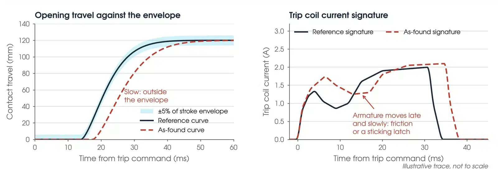
Travel adds the mechanism's motion to the timing: total travel, overtravel, rebound and contact wipe, from a transducer on the mechanism (OMICRON). Velocity is calculated between two points the maker defines, usually through the arcing zone; too slow and the arc may not clear, too fast and the breaker can be damaged (USBR FIST 3-16). Production units stay within the 10% band about the reference curve (AS/NZS 62271.100:2026, Annex G).
The coil current signature shows the armature moving, the latch releasing and the auxiliary contact opening; compare its shape with earlier traces (OMICRON). The minimum pick-up test steps the coil voltage up, about 5 V at a time, until the breaker operates. OMICRON observes that most healthy coils operate below 50% of rated voltage, but this is not an official limit. On spring mechanisms, time the motor recharge after a close (11.3.102.2.5.2). Dynamic resistance measurement (DRM) is a further diagnostic of SF6 arcing contacts that needs an analyser and high DC current.
Which circuit breaker analyser should I use?
Match the analyser to the breaker and the tests the maker asks for. Every instrument below is available calibrated, with leads, from Megavar.
| Instrument | Type | Best used for |
|---|---|---|
| OMICRON CIBANO 500 | Breaker analyser | Timing, travel, coil and motor current, minimum pick-up; supplies the coils; tests with grounded terminals |
| Megger TM1600 | Timing analyser | Opening, closing, bounce and reclose times; motion and coil current with optional modules |
| OMICRON CPX 200 | Multifunction set | Timing of MV breakers using its 125 V DC battery emulation for the coils |
| NOJA Power OSM-27 Test Box | Recloser interface | Trip and close simulation and trip timing on NOJA OSM reclosers, through the RC control cubicle |
Every instrument is available from Hobart, Launceston, Adelaide and Newcastle through Megavar's circuit breaker test equipment hire. If you would rather have the test done, Megavar's engineers carry out circuit breaker testing, substation maintenance and substation commissioning across Australia.
Download the circuit breaker testing guide (PDF)
Frequently Asked Questions
How do I test an electrical circuit breaker?
Isolate and earth it under a permit, connect an analyser, then time open, close, close-open and reclose operations at rated and minimum control voltage.
What is the IEC standard used for circuit breaker testing?
IEC 62271-100, adopted in Australia as AS/NZS 62271.100:2026, read with AS 62271.1:2019.
What is the CRM test in VCB?
Contact resistance measurement on a vacuum circuit breaker: a static micro-ohm test of the closed contacts, separate from timing.
What pole spread is acceptable?
1/6 cycle on opening and 1/4 cycle on closing (AS/NZS 62271.100:2026, 6.101), or the maker's tighter value.
Why test at minimum voltage?
To prove the breaker trips and closes on a depleted battery: 70% (DC) for opening, 85% for closing (AS 62271.1:2019, 6.9).
What is a first trip test?
Timing the first trip of a breaker that has been in service, using clamps on the trip coil and CT secondary circuits.
Can I time a breaker with both sides earthed?
Yes, with an analyser that has a dual earth method.
Does Megavar test as well as hire?
Yes. Our engineers test circuit breakers across Australia. Call 1300 730 499.
Need a circuit breaker tested, or the analyser to do it?
Megavar tests circuit breakers across Australia and hires every analyser in this guide. Call 1300 730 499 or email service@megavar.com.au.