VLF testing applies an AC voltage at a very low frequency, usually 0.1 Hz, to a medium or high voltage cable to prove its insulation, joints and terminations before or during service. The low frequency cuts the charging current a cable draws, so a portable test set can test a circuit several kilometres long. A VLF set does two jobs: a withstand test, which proves the cable holds a set voltage for a set time, and tan delta, which measures the dielectric loss of the whole cable. This guide covers the withstand levels and durations, VLF tan delta, the sheath test, safe set-up and how to judge a result.
Download the VLF cable testing guide (PDF)

What is a high voltage test on cable and how is it performed?
A high voltage test on a cable applies a voltage above operating level between the conductor and the earthed metallic screen, for a set time, with the cable isolated and both ends guarded. If the cable holds the voltage it passes; if a weak point breaks down, it fails during a planned outage rather than in service. On extruded (XLPE and EPR) cable the test is an AC test, either VLF at 0.1 Hz or a resonant set at 20 Hz to 300 Hz. The typical level for any source is 1.5 U0 to 3.0 U0 (IEEE 400-2023 cl 6.2.2).
Why test cables at very low frequency?
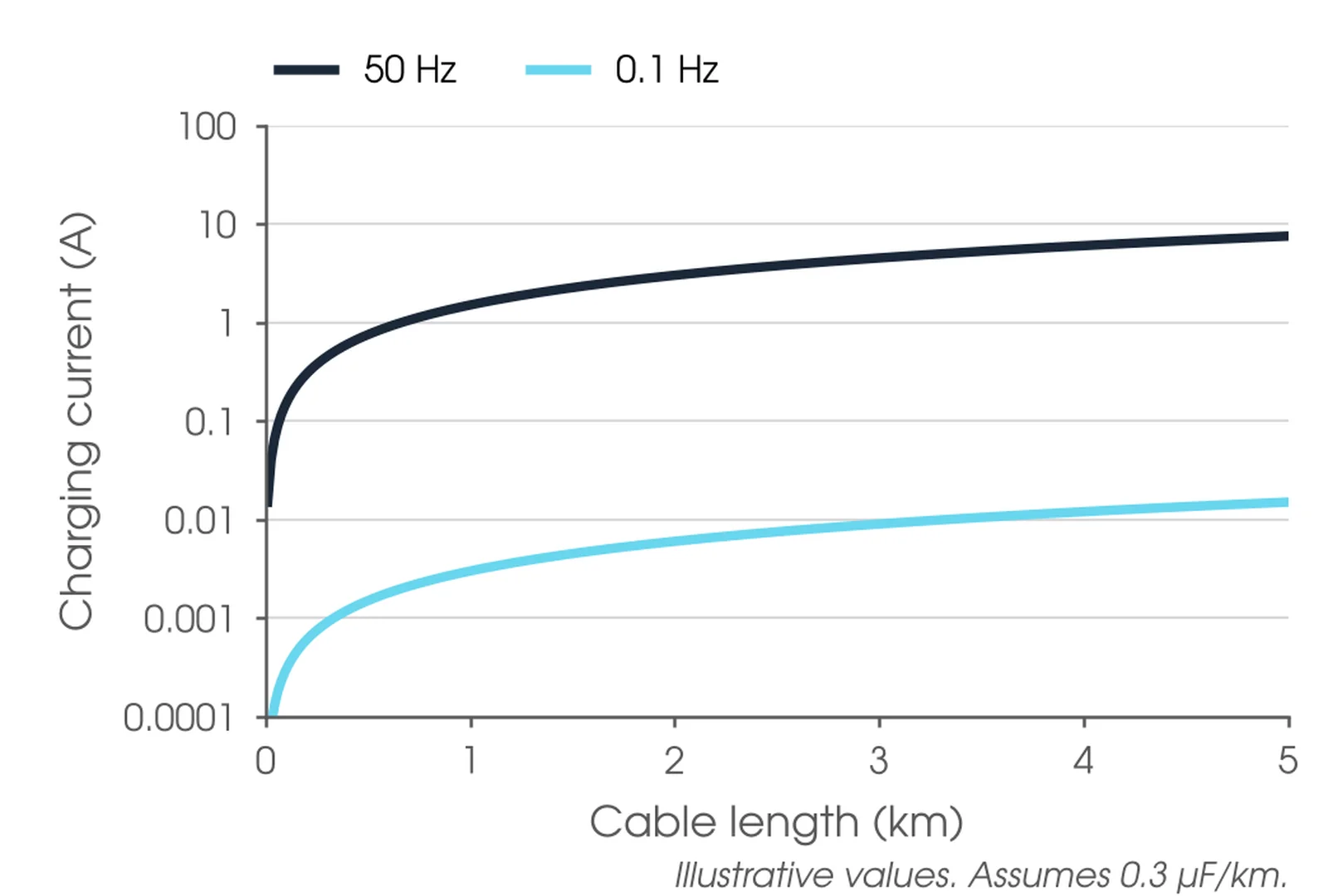
A cable is a capacitor, and the current needed to charge it is I = 2πfCV. At 0.1 Hz the charging current is 500 times lower than at 50 Hz, so a test set of a few tens of kilograms can do work that would need a trailer-mounted resonant system at power frequency.
A VLF withstand is also a controlled way to find a weak cable. At the levels IEEE 400.2-2024 prescribes, a failure on test means the cable was already highly compromised, and because it fails on test, the fault current and collateral damage are limited; that may not be so if it fails in service (cl 5).
When should a cable be VLF tested?
Cable is routine tested in the factory on the drum length. On site, an installation test proves a length before it is jointed, with temporary terminations (IEEE 400-2023 cl 5.2.1). The acceptance test proves the complete circuit, joints and terminations included, before it goes into service. Maintenance tests assess aged cable, usually tan delta first and then a withstand at a lower level. After a fault repair, the circuit is retested before it is re-energised.

Where is VLF testing used?
VLF testing covers shielded cables rated 5 kV and above with extruded or paper insulation (IEEE 400.2-2024 cl 1.1). The table shows the common situations, what the test finds and the usual test.
| Cable or situation | What the test finds | Usual test |
|---|---|---|
| New XLPE or EPR circuit, before service | Installation damage, poor joint and termination workmanship | VLF withstand at acceptance level, 60 min; sheath test |
| Cable length before jointing | Shipping, storage or pulling damage | Installation test with temporary terminations (IEEE 400-2023 cl 5.2.1) |
| Aged extruded cable in service | Water treeing, wet joints, general ageing | VLF tan delta first, then a withstand at maintenance level, 30 min |
| Circuit after a fault repair | Workmanship of the repair | Monitored withstand, 60 min (IEEE 400.2-2024 cl 5.1.1) |
| Mixed XLPE and paper circuit | Wet splices, dry or degraded paper sections | VLF sine with tan delta stability and tip up (Table 6); asset owner rules |
| Cable above 30 kV to IEC 60840 | Accessory installation defects | AC 20 Hz to 300 Hz (IEC 60840:2020 cl 16.3); other tests by agreement |
| Outer sheath | Cuts, holes and termite damage that let water reach the screen | Sheath test, metallic screen to earth |
What VLF test voltage should I use?
IEEE 400.2-2024 Table 3 sets VLF withstand levels by cable rating and test type. For an 11 kV cable the sine levels are 14 kV rms for an installation test, 16 kV rms for acceptance and 13 kV rms for maintenance; for 33 kV they are 37, 42 and 31 kV rms. Cosine-rectangular levels are the sine values times √2 (Table 3 Note 6). The maintenance level is about 75% of the acceptance level (Note 3), and where a cable runs below its rating, maintenance tests use the operating voltage class (Note 1).
AS/NZS 1429.1:2006 sets no VLF level. Its informative Appendix F2 suggests a 24 h test at normal operating voltage, or a higher AC voltage below power frequency as agreed between purchaser and installer. Asset owners set their own levels: Western Power's Distribution Commissioning Manual (2024), for example, sets 3 VN for 60 min at 0.01 Hz to 1.0 Hz, which is 14 kV rms on 11 kV and 41 kV rms on 33 kV, reduced to 80% for existing cable and 60% for cable more than 30 years old.
Our recommendation is to use the asset owner's specification where there is one; otherwise test to IEEE 400.2-2024 Table 3, and name the source of the level in the test plan. Do not raise the voltage to shorten the test: going above 3 U0 to compensate for a shorter time does not replicate a lower voltage, longer test (cl 5.1.1).
Is 33kv HV or mv?
Both terms are used for it. AS/NZS 1429.1:2006 covers polymeric cables from 1.9/3.3 (3.6) kV up to 19/33 (36) kV, the range the cable industry usually calls medium voltage. For installation and safety purposes, AS 2067:2016 cl 1.4.34 defines high voltage as exceeding 1,000 V a.c., so a 33 kV cable is HV work.
How does a VLF test work?
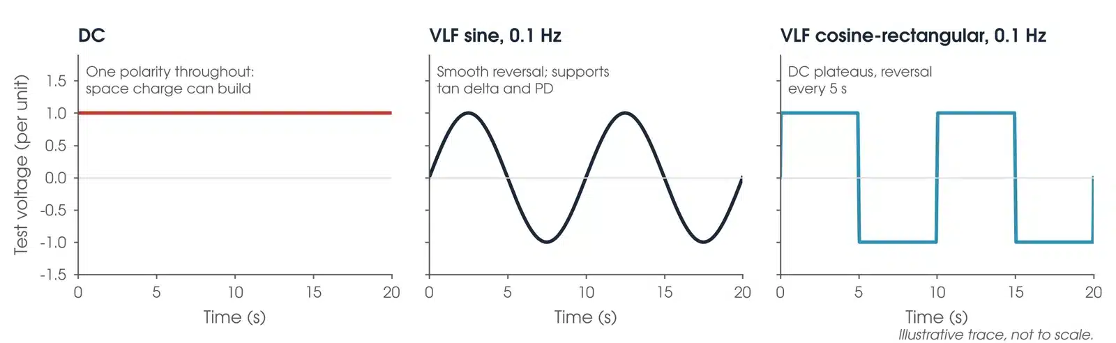
A VLF set applies AC between the conductor of the phase under test and its earthed metallic screen. There are two waveforms. A sine set gives a smooth 0.1 Hz sine. A cosine-rectangular set holds DC plateaus and reverses polarity every 5 s, through transitions equal to frequencies of 30 Hz to 300 Hz (IEEE 400.2-2024 cl 3.1 and 5.2). Both are accepted for a withstand; only a sine supports tan delta.
A simple withstand records only whether the cable held the voltage. A monitored withstand records tan delta, and often partial discharge, through the hold, so the result shows how the cable behaved and not only that it survived (cl 3.1). Partial discharge has its own guide in this series.
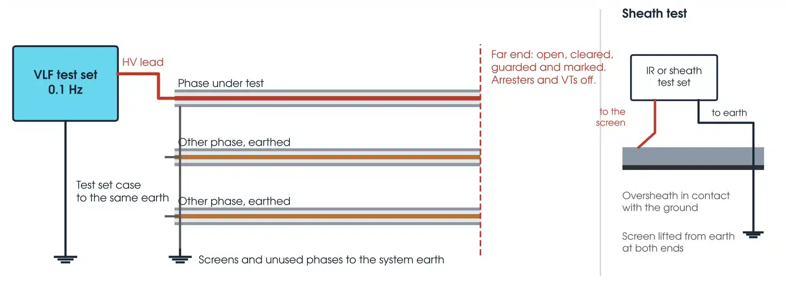
The connection rules are the same on every circuit: one phase at a time, with its screen and the other phases earthed; far ends open, cleared, cordoned off and marked (cl 4.1); surge arresters, VTs and motors disconnected where possible (cl 4.1); and the test set case and all exposed metal bonded to a single system earth at the test site (cl 4.2). Check the set's load rating against the cable capacitance before mobilising. Halving the frequency doubles the length a set can test, but 0.05 Hz results do not trend against 0.1 Hz results (HV Inc, 2021).
What does a tan delta test measure?
A tan delta test measures the dielectric loss of the whole cable: the ratio of the loss current to the capacitive current, tan δ = IR / IC (IEEE 400-2023 cl 6.3.1). A perfect cable is a pure capacitor with almost no loss. Water trees, moisture, corroding screens and degraded accessories add loss, and the way the loss changes with voltage and with time tells the engineer which. Tan delta grades the overall condition of a phase; it cannot locate a single defect in extruded insulation (IEEE 400.2-2024 cl 5.4).
What are the differences between VLF and Megger testing for cables?
They answer different questions. A Megger, or insulation resistance, test applies a DC voltage of up to a few kilovolts and reads the resistance of the insulation; it finds a gross fault or wet insulation but says little about a joint that will fail at service stress. A VLF test applies AC above operating voltage and proves the cable holds it, which is what finds installation damage and poor workmanship. The two work together: insulation resistance before the VLF test, and again after it. Insulation resistance testing has its own guide in this series.
What is the sheath test?
The sheath test proves the outer sheath that keeps water away from the metallic screen. The screen is lifted from earth at both ends and a DC voltage is applied between the screen and earth; the ground around the sheath forms the other electrode (IEC 60840:2020 cl 16.2). AS/NZS 1429.1:2006 Appendix F4 suggests an insulation resistance tester of at least 1,000 V between the outermost metallic layer and earth, with no acceptance value. Asset owners set the value: SA Power Networks requires at least 100 MΩ on new cable and 10 MΩ on existing cable at 1,000 V for 1 min (TS105, 2021), and Western Power at least 1,000 MΩ on new cable and 100 MΩ on old cable with a 5 kV tester (2024).
How do I set up a VLF test safely?
A VLF test puts the full test voltage along the whole cable, so the hazards are at both ends. Four steps come before any lead is connected:
- Confirm the access permit covers the whole cable, both ends, and any temporary removal of earths. Permit earths are removed and replaced only by the person the asset owner authorises.
- Confirm at both ends, with the permit issuer, that the cable is isolated, proved dead and earthed.
- Disconnect arresters, VTs and anything else that would load the test, and record what was removed.
- Barricade and sign the far end and keep voice contact with it throughout the test (IEEE 400-2023 cl 4).
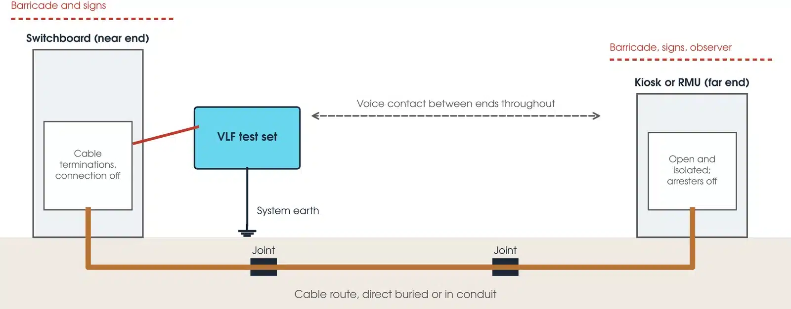
Three hazards are specific to cable testing. A cable holds charge after the test and can recharge by dielectric absorption, so reduce the voltage slowly to zero, discharge, monitor the discharge and then earth (IEEE 400.2-2024 cl 4.1). An open switch or air gap at an isolation point must hold the VLF voltage with the other side at line voltage; check the device with its manufacturer (cl 4.1). And degraded insulation can break down before the test is stopped, so have crews ready to repair a joint, termination or section (cl 5.1.2).
The test is for competent, authorised testing personnel working under the asset owner's safety rules. At Megavar that means assessed testers, with less experienced staff working under direct supervision.
This guide describes general practice for competent HV testing personnel. It is not a work procedure. Work under the asset owner's safety rules, the access permit and a site-specific safe work method statement. Manufacturer and asset owner criteria take precedence over the general guidance here.
How do I make the measurement?

- Check records. Cable type, rating, length, capacitance, joints and route. Time domain reflectometry can confirm length and accessory positions (IEEE 400.2-2024 cl 5.1.2).
- Sheath and insulation resistance. Sheath test, then insulation resistance core to screen. A gross fault will not survive the VLF test.
- Connect. One phase at a time, screens and other phases earthed, terminations clean and in good repair (cl 5.4.2).
- Tan delta ramp. On aged cable, measure at 0.5, 1.0 and 1.5 U0, with at least six readings at each step, 10 s apart at 0.1 Hz and correspondingly longer apart at lower frequencies (cl 5.4.2). Stop if tan delta rises sharply from 0.5 to 1.0 U0.
- Withstand hold. Raise to the test level and hold: 60 min on a new circuit, 30 min on an aged one, at 0.1 Hz. Below 0.1 Hz, consider extending the hold so the cable sees enough cycles, and record the frequency and duration. On a breakdown, record the voltage and the time on test (cl 5.3 and Annex D).
- Ramp down and discharge. Reduce slowly to zero, discharge and earth (cl 4.1).
- Insulation resistance after. Repeat the insulation resistance test. Western Power requires it after every VLF test (2024).
- Restore. Reconnect removed plant and restore earths per the permit.
Keep the voltage ramp the same from test to test, and record the cable temperature. Both affect the result (cl 5.4 and Annex D).
How to do a tan delta test?
Tan delta is measured with a sine VLF set and a tan delta module on an isolated, discharged cable with clean terminations. The voltage is set at 0.5 U0 and raised to 1.5 U0 in steps of 0.5 U0, taking at least six readings at each step, 10 s apart at 0.1 Hz and correspondingly longer apart at lower frequencies (IEEE 400.2-2024 cl 5.4.2). If tan delta rises sharply between 0.5 U0 and U0, stop: the cable is highly degraded and raising the voltage risks starting electrical trees, so the result is graded action required (cl 5.4). Compute the results before deciding on a withstand, because they guide its duration.
What are the common VLF testing mistakes?
| Mistake | What it does to the result |
|---|---|
| Arresters or VTs left connected | They load or clamp the test voltage, or are damaged by it |
| Wrong U0 | Acceptance tests use the component rating; maintenance tests use the system voltage (IEEE 400.2-2024 cl 3.1) |
| Dirty terminations | Surface leakage raises tan delta and can track |
| Tan delta on a cosine-rectangular set | That waveform does not support it (cl 5.2) |
| Pushing on after a sharp tip up | Risks starting electrical trees in a highly degraded cable (cl 5.4) |
| Shortening a retest | Monitoring cannot cut the 60 min retest after a failure (cl 5.1.1) |
| Trending different frequencies | 0.05 Hz and 0.1 Hz results are not comparable |
| DC hipot on aged XLPE | See the section on DC below |
How do I read a VLF test result?
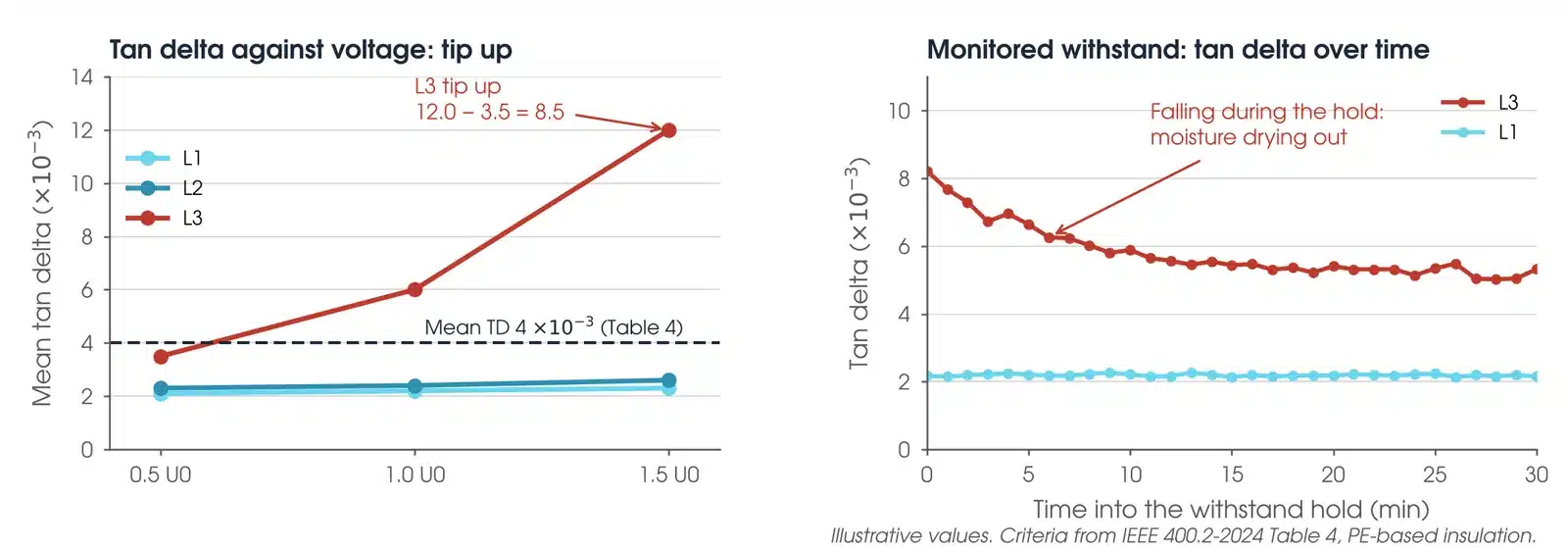
A withstand result is simple: the cable passes if it holds the test voltage for the full hold without breakdown. Tan delta is judged on three features, in order of sensitivity: stability over time at constant voltage (SDev), change with voltage (tip up, TU), and the mean value at U0 (IEEE 400.2-2024 cl 5.4). The condition grade is set by the worst of the three.
What is a good tan delta value?
For aged PE, XLPE and TRXLPE cable at 0.1 Hz, IEEE 400.2-2024 Table 4 grades the result as no action required when SDev at U0 is below 0.1, tip up is below 5 and mean tan delta at U0 is below 4, all in units of 10⁻³. Action is required when SDev is above 0.5, tip up above 80 or mean tan delta above 50. Values between are further study advised. Filled insulations such as EPR have their own criteria in Table 5, and paper cable in Table 6, where a negative tip up can point to wet splices.
The tables apply to maintenance tests on cable in service for five years or more, are based on North American data, and should not be applied directly to new cable (cl 5.4). On new cable, stability and tip up are the most useful features to baseline; compare phases of the same circuit, and compare each test with the last at the same frequency.
What does a bad VLF test result look like?
| Pattern | What it usually means |
|---|---|
| Breakdown during the hold | A weak point failed. Locate it, repair, and retest for 60 min (IEEE 400.2-2024 cl 5.1.1) |
| Tan delta rises with voltage | Water treeing in extruded cable, or discharging paper (IEEE 400-2023 cl 6.3.1) |
| Tan delta falls over time or with voltage | May indicate moisture in accessories (IEEE 400-2023 cl 6.3.1) |
| High, unstable readings | Poor stability is the most sensitive sign of ageing (IEEE 400.2-2024 cl 6) |
| One phase unlike the others | Localised loss in that phase, often a joint or termination |
Is my result OK?
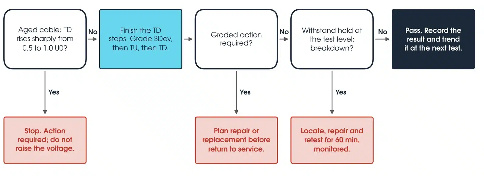
On aged cable, start with tan delta. If it rises sharply from 0.5 U0 to U0, stop: the grade is action required and the voltage is not raised further. Otherwise finish the steps and grade stability, tip up and mean value. If the grade is action required, plan repair or replacement before the circuit returns to service. If not, hold the withstand at the test level. A breakdown means locate, repair and retest for 60 min, monitored; no breakdown is a pass, to be recorded and trended at the next test. New cable goes straight to the withstand.
How do I calculate tan delta?
The instrument calculates tan delta itself as the ratio of loss current to capacitive current. The features are then worked out from the readings (IEEE 400.2-2024 cl 5.4.2): mean tan delta is the average of the readings at one voltage, SDev is their standard deviation, and tip up is the mean at 1.5 U0 minus the mean at 0.5 U0.
Worked example: phase L3 reads a mean of 3.5, 6.0 and 12.0 × 10⁻³ at 0.5, 1.0 and 1.5 U0, with SDev 0.08 × 10⁻³ at U0. Tip up is 12.0 minus 3.5, which is 8.5 × 10⁻³, in the 5 to 80 band: further study. Mean tan delta at U0 is 6.0 × 10⁻³, in the 4 to 50 band: further study. SDev is below 0.1. The worst feature sets the grade, so L3 is further study advised.
What should a VLF test report include?
The method, waveform, frequency, test voltage as peak and rms, and duration (IEEE 400-2023 cl 5.6); pass or fail, and on a failure the failure voltage, time on test and the component that failed; mean tan delta, SDev and tip up per phase with the grade and the cable temperature; and the cable, its length and accessories, the criteria used, and the instrument serial number and calibration date.
Why is DC no longer used on XLPE cable?
High voltage DC builds space charge in aged extruded insulation, which can cause failure when AC is reapplied (IEEE 400-2023 cl 6.2.2). IEEE 400-2023 rates the HVDC withstand on aged extruded distribution cable "Do not use" (Table C.1), and AS/NZS 1429.1:2006 Appendix F1 states that DC testing of the primary insulation is not recommended. Australian asset owners have followed: Western Power states that HV XLPE cable must not be tested with DC hipot equipment (2024), and SA Power Networks limits XLPE testing to 5,000 V DC (TS105, 2021).
DC still has a place. Western Power still specifies a DC hipot on paper-insulated belted cable (2024), and the sheath test is a DC test on the oversheath, not on the primary insulation. A 5,000 V insulation resistance test is not an HV DC test (TS105 cl 8.3). If a specification calls for a DC hipot on XLPE, raise it with the asset owner before testing.
Which VLF and cable test sets should I use?
Match the set to the cable rating, length and test. Every instrument below is available calibrated, with leads, from Megavar.
| Instrument | Rating | Best used for |
|---|---|---|
| HVA 60kV VLF Cable Test Set | 60 kV peak, 0.1 Hz sine | Withstand on cables rated to 36 kV, including 33 kV acceptance; DC and sheath test modes |
| HVA 28kV VLF Test Set with Integrated Tan Delta | 28 kV, 0.1 Hz sine | Tan delta and withstand on 11 kV cable; tan delta to 1.5 U0 on 22 kV |
| SUTE 300 kV HV Resonant Test Set | 300 kV, 25 to 300 Hz | AC withstand on HV cable to IEC 60840 cl 16.3 |
| Phenix 500 kV HV Resonant Test Set | 500 kV, 45 to 300 Hz | AC withstand on long and transmission class cable circuits |
| Phenix BK130 130 kV Hipot Test Set | 130 kV AC | Power frequency withstand on short cables, terminations and switchgear |
| Megger MIT1020 10kV Insulation Resistance Tester | 10 kV DC | Insulation resistance before and after the withstand |
Every instrument is available through Megavar's cable testing equipment hire. If you would rather have the test done, Megavar's engineers carry out HV cable testing across Australia.
Download the VLF cable testing guide (PDF)
Frequently Asked Questions
How long is a VLF test?
60 min on a new circuit or after a repair, and 30 min on an aged circuit, at 0.1 Hz (IEEE 400.2-2024 cl 5.1.1). Below 0.1 Hz, consider a longer test. Important feeder circuits can be extended to 60 min.
What is the IEC standard for cable insulation resistance testing?
There is no single one. AS/NZS 1429.1:2006 has no insulation resistance test for the cable insulation, and IEC 60840:2020 uses an AC test after installation. Asset owners set their own insulation resistance criteria, for example SA Power Networks in TS105.
Can a VLF test damage a good cable?
IEEE 400-2023 cl 5.2.2 states that testing well-installed, defect-free new cable below factory levels is not likely to cause a significant reduction in its service life. The risk is in raising the level or the duration beyond the recommended values.
What is the difference between VLF sine and cosine-rectangular?
A sine set gives a smooth 0.1 Hz sine and supports tan delta. A cosine-rectangular set holds DC plateaus and reverses every 5 s; tan delta is not available with it (IEEE 400.2-2024 cl 5.2).
Can I VLF test a cable with mixed XLPE and paper sections?
Yes, with a sine source. IEEE 400.2-2024 rates the simple withstand good for mixed insulation; for tan delta use stability and tip up rather than the absolute value (cl 5.4).
Is VLF used on transmission cables?
For cables above 30 kV to IEC 60840:2020 the after-installation test is AC at 20 Hz to 300 Hz (cl 16.3), which is normally a resonant test set. IEEE 400.2-2024 gives VLF levels up to 138 kV.
Does a VLF test find partial discharge?
Not on its own. Partial discharge is measured with a separate PD system, often during the same VLF energisation. It has its own guide in this series.
Does Megavar test as well as hire?
Yes. Our engineers test MV and HV cables across Australia. Call 1300 730 499.
Need a cable tested, or the VLF set to do it?
Megavar tests MV and HV cables across Australia, and hires the VLF, resonant and insulation resistance test sets in this guide. Call 1300 730 499 or email service@megavar.com.au.