Earth resistance testing measures how well an earth electrode or a substation earth grid carries fault current into the ground. On a single electrode it is one resistance reading. On a substation it is a set of measurements made against the earthing design: the grid impedance, the earth potential rise (EPR) during a fault, and the touch and step voltages a person could be exposed to. This guide explains the fall-of-potential method, soil resistivity testing, earth grid current injection, step and touch voltage measurement, and how Megavar engineers judge the results against the design and the Australian earthing guides.
Download the earth resistance testing guide (PDF)

What is earth resistance testing?
Earth resistance testing is the measurement of the resistance, or on a large system the impedance, between an earthing system and remote earth. For a driven rod or a small group of rods, a portable earth tester and three probes give the answer in minutes. For a substation earth grid, the resistance is only the starting point: what decides whether the site is safe is the voltage that appears on the ground and on touchable metalwork when fault current flows, so a substation earthing test also measures those voltages directly.
The tests sit at different points in the life of an earthing system. Soil resistivity is measured before the grid is designed. Continuity of every joint and bond is proven during construction. The current injection test, with its touch and step survey, is the commissioning test and sets the baseline. Continuity and repeat tests follow at the network owner's interval, and again after any change: an extension, nearby construction, theft of earth conductors or a new service connected to the site.

Why earthing testing is about voltage, not just resistance
An earth fault on a 33 kV or 132 kV network can drive several thousand amperes into a substation earth grid. The grid impedance, multiplied by the share of that current that actually flows into the local soil, sets the earth potential rise of the whole site. That rise is distributed across the ground surface, the fences, the structures and any metallic service that leaves the site. A person touching a structure while standing a metre away, or stepping across the ground near the grid, is exposed to part of that rise for as long as the fault takes to clear. Whether the installation is safe depends on that voltage, its duration and the resistance of the person's body and footwear, not on whether the grid measures 0.5 ohms or 1.5 ohms.
That is why Australian practice, set out in AS 2067:2016, Substations and high voltage installations exceeding 1 kV a.c., and in the Energy Networks Australia Power System Earthing Guide, Part 1: Management Principles (ENA DOC 025-2022, EG-0), defines compliance in terms of permissible touch and step voltages for the fault clearing time, and why a competent earthing test measures those voltages directly.
Earth grids are buried, so a defect can sit unnoticed for years. A 2025 Doble conference paper from Alabama Power describes a distribution substation where a defective below-grade exothermic weld had separated the neutral riser from the grid, probably since construction. The defect only showed itself when a crew unbolted a transformer lead and set it on the tank cover: an arc formed, and 145 A was then found flowing in their temporary earths. A continuity test of the grid connections finds that kind of break before it finds a person.
What is the proper procedure for testing an earthing system?
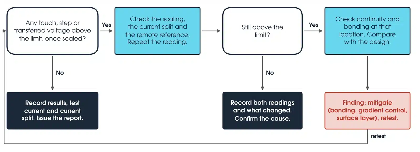
The proper procedure for a substation earthing system runs through seven steps, grouped below, and the measurements only mean something when they are compared with the earthing design that was done for the site.
- Review the design. Obtain the soil resistivity survey, the grid drawing, the design fault current and clearing time, the current split assumptions (how much fault current returns through cable sheaths and overhead earth wires rather than the soil) and the calculated EPR and touch and step limits.
- Prove continuity and bonding. Measure the resistance of every bond the earthing design requires, from structures, fence panels, gates, transformer tanks, switchgear earth bars and cable sheath bonds back to the grid, with a high-current continuity tester. OMICRON recommends test currents of 50 A and above, because small changes in joint resistance that low-current testers miss show up at high current. A four-probe connection keeps lead resistance out of the result (EG-1, clause 14.3). The same test confirms that fences and metalwork designed to be separately earthed are still segregated; never add a bond just because a reading is high. IEEE Std 81-2025 (clause 10.5.6) treats more than 1.0 ohm as clearly not bonded and gives 2 to 5 milliohms across a single connector as a possible owner target. A reading out of family with its neighbours is a defect to fix before the injection test.
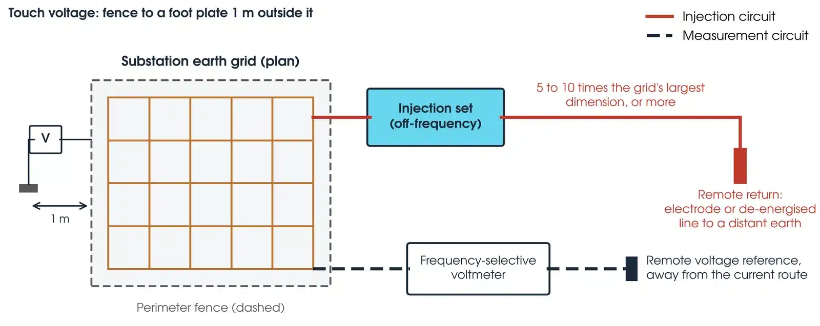
- Measure the grid impedance by current injection. Inject a known current into the grid against a remote return and measure the resulting rise of the grid voltage against a separate remote reference. The voltage rise divided by the current entering the soil gives the grid impedance. The EPR is the measured rise scaled by the ratio of the soil-return fault current to the soil-return test current, so the current leaving by sheaths and earth wires must be measured (EG-1, clause 14.6.3.3). Where the clearing time is under 0.5 s the fault current is first increased by the decrement factor for the system X/R (EG-1 Table 8.3).
- Measure touch and step voltages. While the injection current is flowing, measure the voltage between each touchable structure and a point one metre away on the ground, and across one metre of ground along the paths people walk: the fence, the gates, the entrance, the operating positions and the site boundary. Scale each reading to the design fault current and compare it with the permissible limit for the clearing time.
- Check transferred potentials. Measure the voltage transferred to metallic services leaving the site, such as telecommunications cables, pipelines, fences and LV neutrals, and confirm they are within the limits for those services.

This is the scope of Megavar's earthing design and testing service, which takes a site from the soil resistivity survey and grid design through to step, touch and earth resistance testing, so the design assumptions are the ones checked on site.
Earth grid testing by current injection
The earth grid current injection test is the definitive test of an installed substation earthing system. A test current is injected into the grid from a portable source and returned through a remote electrode, or through a de-energised overhead line or cable, to a distant earth. IEEE Std 81-2025 (clause 8.3.4) places the current return typically 5 to 10 times the largest dimension of the grid, and AS 2067 Appendix H (H6.1) notes that making mutual resistance effects negligible can need 30 times. EG-1 prefers the potential lead to run at 90 degrees to the injection line, to limit induced voltage. Using a disconnected power line as the return reflects the real fault current distribution and avoids running a long lead across public land.
The practical problem is that a few amperes of test current are swamped by the 50 Hz currents already flowing in the soil from normal network unbalance. The solution is to inject at a frequency close to, but not at, 50 Hz and to measure with a frequency-selective voltmeter tuned to the test frequency; the results are then interpolated to mains frequency. At those frequencies EG-1 (clause 14.6.2.2) notes that an amplifier output of 1 A to 30 A usually gives sufficient accuracy, and AS 2067 Appendix H (H5) gives 2 A to 20 A as common. AS/NZS 3835.2:2006 (clause 6.13) requires the test current to be kept to the minimum that gives satisfactory readings, and the measured EPR must in no case exceed 60 V. Megavar's fleet for this work is the Red Phase 1.5 kVA earth current injection set, which delivers typically up to 25 A, with the Red Phase 4025E frequency-selective multimeter or the Mitton TVM1100 tuned voltmeter, which tunes from 45 Hz to 65 Hz and rejects power frequency noise by better than 70 dB. Where more current is needed, the OMICRON CPC 100 with the CP CU1 coupling unit injects 100 A at up to 50 V over a power line return. All of it is available as earth testing equipment hire.
| Measurement | What it gives | Compared with |
|---|---|---|
| Grid voltage rise against a remote reference divided by injected current | Grid impedance in ohms; earth potential rise when scaled to fault current | Design grid impedance and design EPR |
| Voltage between structure and ground at 1 m, scaled | Prospective touch voltage at each location | Permissible touch voltage for the fault clearing time and surface layer |
| Voltage across 1 m of ground along walking paths, scaled | Prospective step voltage | Permissible step voltage |
| Voltage on services leaving the site, scaled | Transferred potential | Limits for telecommunications, pipelines and LV systems |
| Current measured in each cable sheath, earth wire and return path during injection | Actual current split | Design current split assumption |
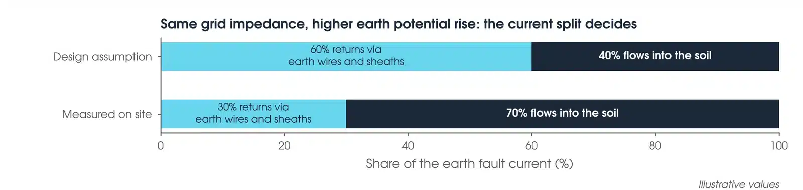
The current split measurement is the one most often left out and the one that most often changes the answer. Overhead earth wires and cable sheaths carry part of the fault current away from the soil, and the reduction factor is the share that still returns through the soil (EG-1, section 8.12). If the design assumed 60 per cent of the fault current returns through cable sheaths and the test shows 30 per cent, the EPR is higher than designed and the touch voltage limits may be exceeded even though the grid impedance measured correctly.
Step and touch potential: measurement and limits
Touch voltage is the voltage between a hand on a structure and the feet on the ground, usually taken one metre away. Step voltage is the voltage between two feet one metre apart on the ground. OMICRON notes that a 2 m distance is used where hand-to-hand contact is likely or people may lie on the ground, such as in leisure areas. Both are measured during the injection test as prospective values with a high impedance voltmeter, because the design criteria in AS 2067 (clause 8.8) and EG-1 (clause 14.6.3.4.1) are prospective touch voltage criteria. Where a prospective reading looks high, a loaded check measures the voltage across a simulated body impedance of about 1000 ohms, the figure EG-1 gives and the body resistance IEEE Std 80-2013 (clause 7.1) uses throughout, with the feet represented by weighted 8 cm radius discs on a wetted surface. A loaded reading is never compared with a prospective limit. Readings are taken where a person is most likely to be during a fault and where the gradient is steepest: the perimeter fence and gates, the entry path, operator positions at switchgear and the transformer, and the corners of the grid where the current density is highest. OMICRON's experience is that the highest touch voltages usually occur on the outside of fences that are not properly bonded, and on nearby metal such as streetlights and traffic signs.
The permissible values are not fixed numbers. AS 2067 (clause 8.3.2) requires body current limits and path impedance to be derived from AS/NZS 60479.1, and the limit for a location depends on the fault clearing time and the surface layer. Australian designs express it as an EG-0 safety criteria case (Table 4-2): TSI inside a transmission substation, ZSI inside a zone substation, and cases such as TU, DU and TDB outside the fence. A crushed rock surface layer, usually 0.08 m to 0.15 m deep (IEEE Std 80-2013, clause 12.5), raises the permissible touch voltage, and a site that clears faults slowly has a much lower limit than one that clears quickly. The test report states the limit used at each location, the clearing time it was derived from, and the measured and scaled value against it. A test-level reading is never compared directly with a fault-level limit.
What is the 3 point test for earthing?
The 3 point test is the fall-of-potential method for measuring the resistance of an earth electrode or a small earth grid. It uses three connections: the earth electrode under test (E), a current probe (C) driven into the ground some distance away, and a potential probe (P) driven in between them. The tester passes a current between E and C and measures the voltage between E and P; the ratio is the earth resistance.
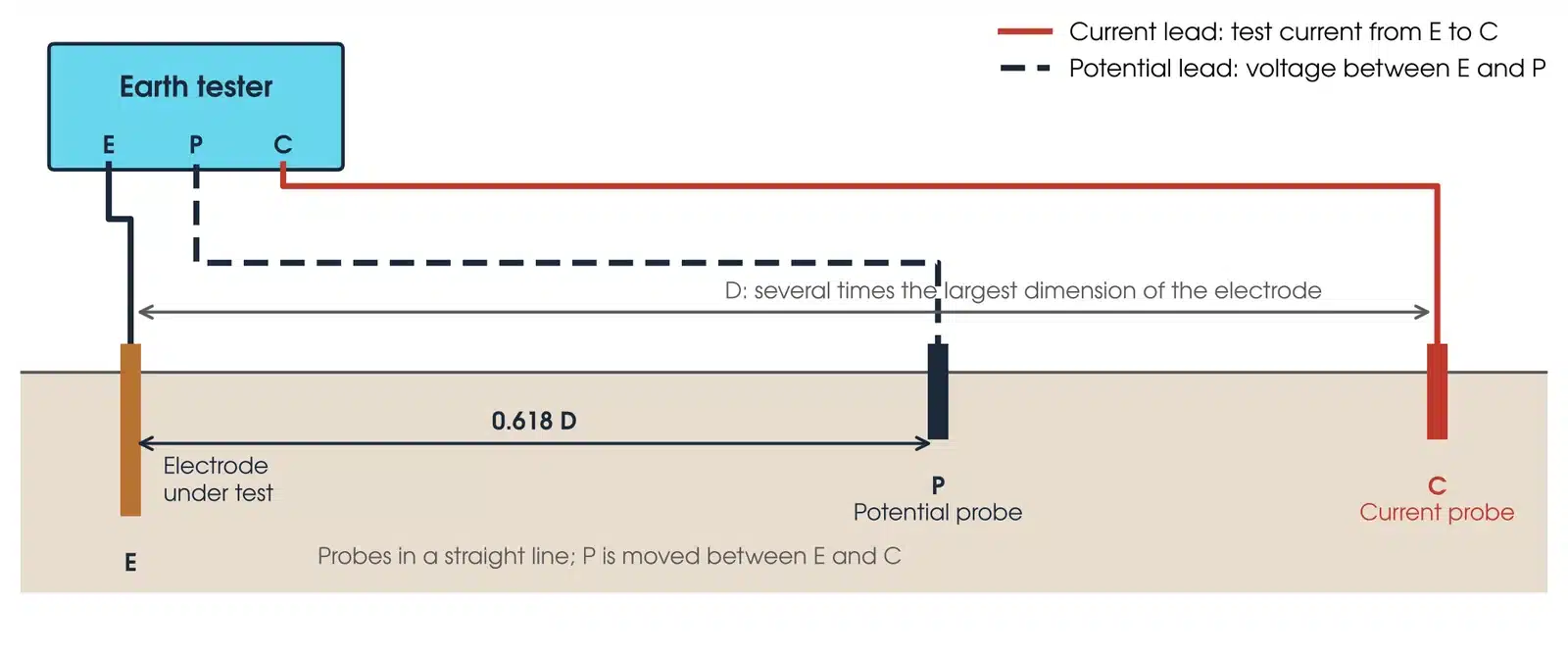
The potential probe is moved along the line between E and C and the resistance plotted against distance. As Megger's guide explains, the reading rises, levels off, then rises again near C, and the level part is the true electrode resistance. The 61.8 per cent rule places the potential probe at 61.8 per cent of the distance from E to C, which lands on the flat region for a simple electrode in uniform soil, provided the electrical centre of the electrode is known and the current probe is far enough away. Megger's probe table gives the scale: for a 30 m by 30 m electrode system, with a diagonal of about 43 m, P sits about 111 m and C about 180 m from the electrode.
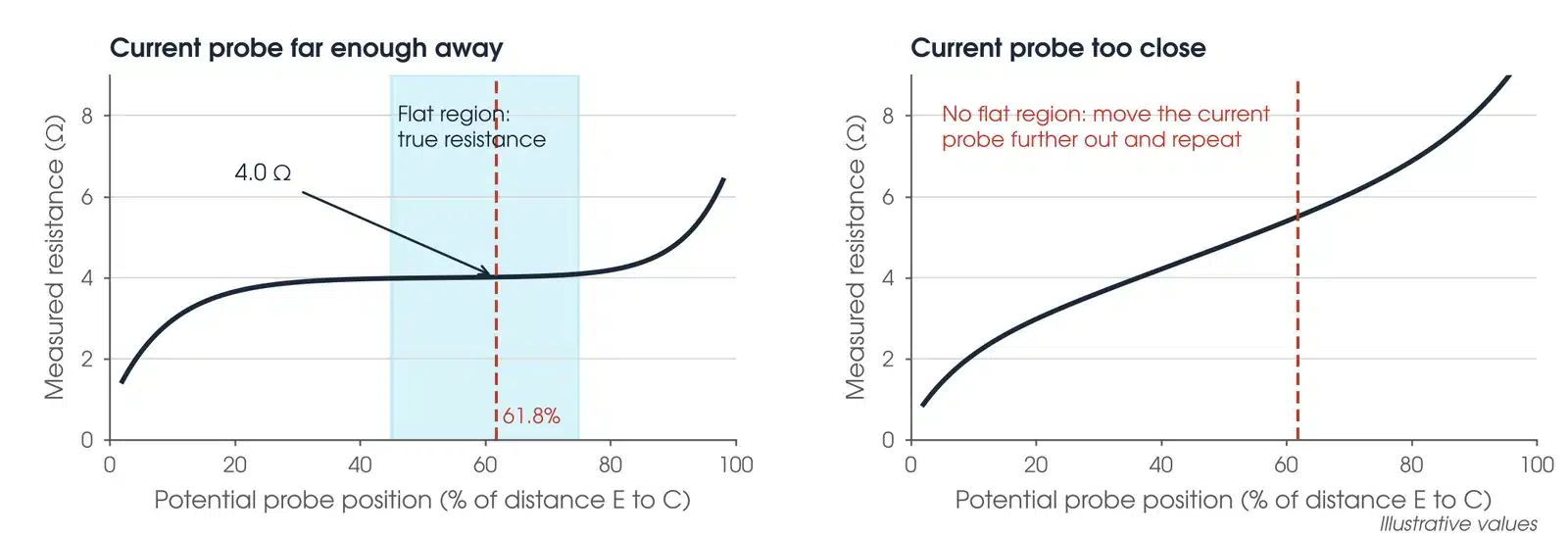
A single reading at 61.8 per cent proves nothing on its own; it is the flat region of the plotted curve that proves the result. A single electrode has to be disconnected, or the whole connected system is measured, but only under the approved isolation with temporary earthing in place. Check the current and induced voltage in the earth conductor first; a zero reading alone does not make disconnection safe (IEEE Std 81-2025, clause 5.3). Megavar runs fall-of-potential and soil resistivity tests with the AEMC 6471 ground resistance tester, from its earth testing rental range. On a large substation grid the current probe would need to be hundreds of metres to kilometres away for the curve to flatten, which is why the current injection test replaces the 3 point test there.
Clamp-on earth testing
A clamp-on tester induces a test voltage into an earth conductor and measures the resulting current, giving the loop resistance of that electrode in series with every other earth it is connected to in parallel. It needs no disconnection and no probes, which makes it quick for checking individual electrodes on a multiple-earthed system such as a distribution feeder. It cannot be used on an isolated electrode, and it gives a meaningless reading on a substation grid where the electrode under test is the dominant low-resistance path.
Testing large substation earth grids
Large grids push the fall-of-potential method past its limits. Megger's guide notes that the current probe ideally sits 10 times the maximum dimension of the ground system away, which for a 90 m grid means a probe about 900 m out, and that large ground systems typically measure below 0.5 ohms, so instrument resolution and noise rejection decide whether small differences can be seen at all. Where a full curve is impractical, the slope method takes readings at 20, 40 and 60 per cent of the current probe distance and fits them to a model of the curve, so no flat region is needed. EG-1 (clause 14.6.3.5) cautions that many low power portable meters are not appropriate below 5 ohms, that the 61.8 per cent rule suits small localised systems only, and that larger systems need a current lead at least 5 times the largest grid diagonal. AS/NZS 3835.2:2006 (clause 6.8.3) states that a self-contained instrument should not be used to measure the impedance of a large HV site. For commissioning a transmission or zone substation, the current injection test with a remote return remains the definitive method.
Soil resistivity testing: the Wenner method and calculation
Soil resistivity is measured with the Wenner four-pin method before an earth grid is designed. Four probes are driven in a straight line at equal spacing a, a current is passed between the two outer probes and the voltage measured between the two inner probes. The tester reads the resistance R, and the apparent soil resistivity is calculated as ρ = 2πaR, in ohm-metres when a is in metres. The formula holds when the probe depth is small compared with the spacing: AS/NZS 3835.2:2006 (clause 6.16) sets it at less than 5 per cent of the separation.
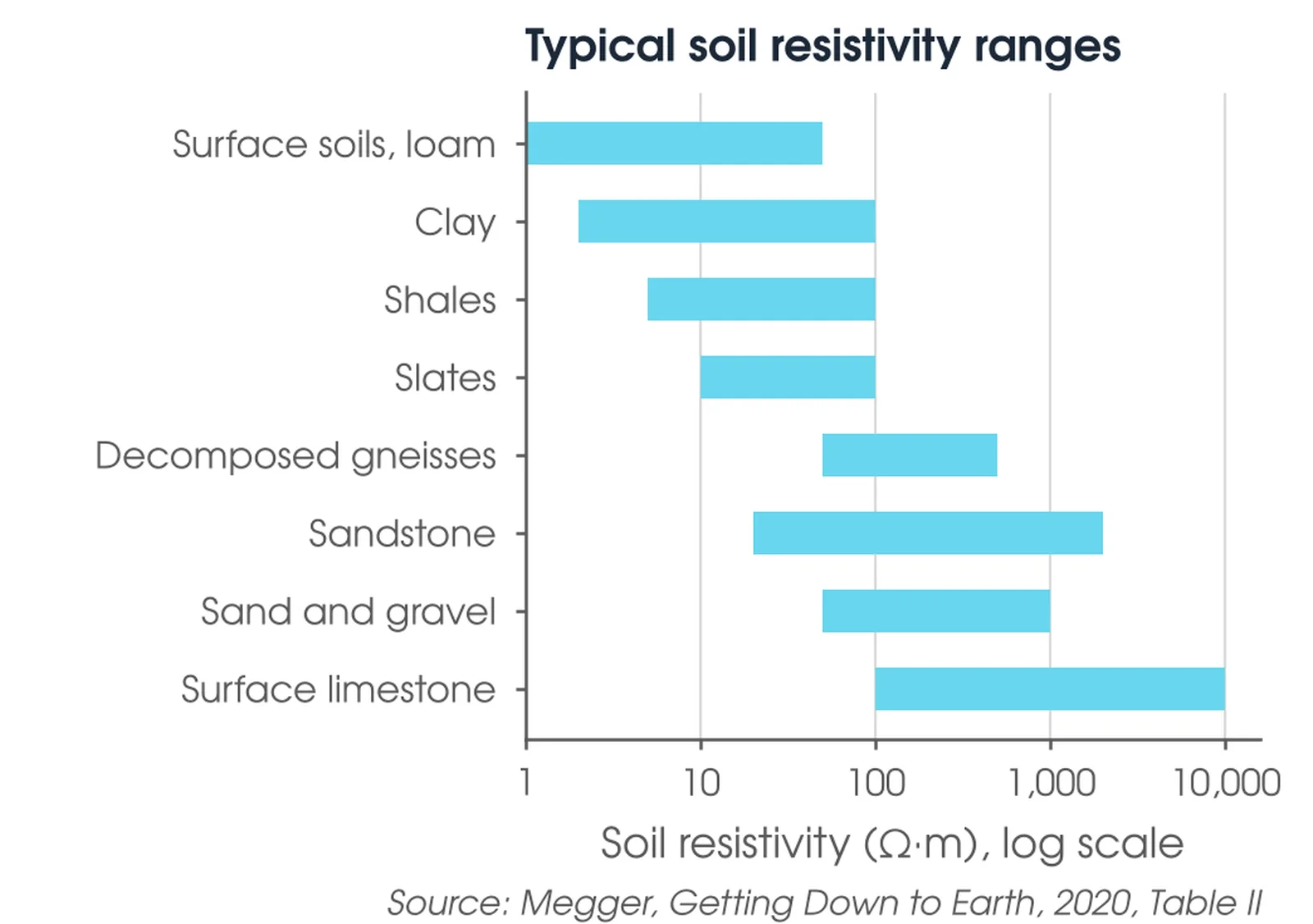
EG-1 (clause 14.5.4.4) recommends accurate inner spacings of about 1 m, which give the upper layer resistivity used for step and touch voltages, and outer spacings larger than the radius or diagonal of the proposed grid. IEEE Std 81-2025 (clause 7.4.3) recommends at least two traverses in different directions, and EG-1 (clause 14.5.4.3) four or more for larger grids. The resistivity is plotted against spacing. The result is a profile of resistivity with depth, because a wider spacing drives the current deeper. That profile is fitted to a two-layer or multi-layer soil model, and the model is what the grid design uses to predict the grid impedance and the surface voltage gradients. Resistivity varies widely: Megger's table runs from around 1 ohm-metre for some loams to 10,000 ohm-metres for surface limestone, and moisture and dissolved salts move it further. Megavar takes soil resistivity readings along multiple traverses and at a range of electrode spacings, and repeats the survey where the site has been cut, filled or otherwise disturbed.
What is the normal reading for earthing?
There is no single normal reading, because the safe value depends on the fault current, the clearing time and the voltages that result, not on the resistance alone. EG-1 (clause 14.1) says tests in most cases measure the resulting voltages and current distributions rather than solely earth resistance. The figures below are working guidance, and the compliance test is always the step and touch voltage measurement, not the resistance.
| Installation | Working guidance | Governing requirement |
|---|---|---|
| Transmission and zone substations | Large substation grids typically measure below 0.5 ohms (Megger); the target is set by the design so that EPR and touch and step voltages meet the limits | AS 2067:2016 and EG-0 touch and step limits for the fault clearing time |
| Distribution substations and pole-mounted plant | Set by the distributor's earthing manual, including whether HV and LV earths are combined or separated | AS 2067:2016, EG-0 and the distributor's earthing manual |
| Wind farm and solar farm collector networks | Set by the design; the interconnected cable sheath system usually gives a low combined impedance, and the test confirms touch voltages at each turbine base and inverter station | AS 2067:2016, EG-0 and the connection agreement |
Two questions that come up alongside this one deserve a one-line answer each. A multimeter on the ohms range is not an earth tester: at best it gives a two-point go or no-go reading against a known good earth (IEEE Std 81-2025, clause 8.3.2), with no remote earth reference and no rejection of the voltages already present in the soil; an earth tester or an injection set is needed. And a continuity check with a multimeter between a socket earth pin and a water pipe is an LV installation check, not an earthing system test, and says nothing about a substation grid.
What are the methods of earthing?
For high voltage installations the methods of earthing refer to how the earth grid is formed and how the system neutral is connected to it. The grid itself is a buried mesh of bare copper conductor with driven rods at the perimeter and at the equipment positions, sized for the fault current and the corrosion life, with the mesh spacing set by the touch voltage design. System neutral earthing is a separate decision: solid earthing of the transformer neutral for most transmission systems, resistance or reactance earthing to limit earth fault current on distribution and industrial systems, and resonant (Petersen coil) or isolated neutrals on some rural distribution networks. The neutral earthing method sets the earth fault current and clearing time, which in turn set the limits the grid is tested against. For LV installations in Australia the method is the multiple earthed neutral (MEN) system; customer LV earthing falls under AS/NZS 3000 and outside the scope of EG-0 (clause 1).
What are the prices of earth resistance tests?
An earthing test for a substation is priced by the site, not per reading. The cost drivers are the size of the grid and the number of touch and step points to be measured, the distance to a usable remote return path for the current injection, whether an outage or a de-energised line is available for the return circuit, the travel and site induction time, and whether a design review and compliance report is required. A single pole earth or small grid tested by fall of potential is a short job; a zone substation injection test with a full touch and step survey is a larger one. Megavar quotes each job individually, and hires the earth testing equipment to contractors who would rather test themselves.
Standards and references for earthing testing in Australia
| Standard or guide | Scope |
|---|---|
| AS 2067:2016 | Substations and high voltage installations exceeding 1 kV a.c.: earthing design requirements and permissible touch and step voltages |
| ENA DOC 025-2022 (EG-0) version 2, Power System Earthing Guide, Part 1: Management Principles | Risk framework and probabilistic touch voltage criteria, including the safety criteria cases (TSI, ZSI and others) in Table 4-2 |
| ENA DOC 045-2022 (EG-1) version 2.0, Substation Earthing Guide | Substation earthing design, construction and testing; section 14 sets out the test methods. A separate guide from EG-0, not a replacement for it |
| IEEE Std 80-2013 | Guide for safety in AC substation grounding: tolerable touch and step voltages and grid design |
| IEEE Std 81-2025 | Guide for measuring earth resistivity, ground impedance and earth surface potentials of a grounding system |
| AS/NZS 60479.1 | Effects of current on human beings: the body current and impedance data AS 2067 clause 8.3.2 requires the limits to be derived from |
| AS/NZS 4853:2012 | Electrical hazards on metallic pipelines: transferred potential limits |
| AS/NZS 3835.1:2006 and AS/NZS 3835.2:2006 | Earth potential rise: protection of telecommunications network users, personnel and plant. Part 2 clause 6.13 sets the 60 V ceiling on measured EPR during a test |
Megavar designs and tests earthing systems for substations, renewable energy projects, BESS and industrial installations across Australia, often as one part of a wider substation commissioning programme, and reports every test against the design it was built to.
Download the earth resistance testing guide (PDF)
Frequently Asked Questions
What is the 3 point test for earthing?
The 3 point test is the fall-of-potential method. Current is passed from the electrode under test to a remote current probe, and the voltage is measured to a potential probe moved along the line between them. Plotting resistance against probe distance gives a curve that flattens at the true value, which for a simple electrode in uniform soil falls at about 61.8 per cent of the distance to the current probe.
What is the proper procedure for testing an earthing system?
Review the earthing design and its fault current, clearing time and current split assumptions; prove at high current the continuity of every bond the design requires, and the segregation of separately earthed fences; measure grid impedance and earth potential rise by off-frequency current injection against a remote return; measure touch and step voltages at fences, gates, operating positions and the boundary and scale them to the fault current; and check transferred potentials on services leaving the site. Compare every scaled result with the limits for the clearing time.
How to calculate soil resistivity test?
Use the Wenner four-pin method: four probes in a line at equal spacing a, current between the outer pair and voltage between the inner pair. The apparent resistivity is ρ = 2πaR, where R is the tester reading, provided the probe depth is small compared with the spacing. Repeat at increasing spacings to profile resistivity with depth, then fit the profile to a layered soil model for the grid design.
What are the prices of earth resistance tests?
Substation earthing tests are priced per site. The drivers are grid size and the number of touch and step points, the distance to a usable remote return path, outage or de-energised line availability for the return circuit, travel and induction time, and whether a compliance report is required. Megavar quotes each job individually.
What is the normal reading for earthing?
There is no single normal reading, because safety depends on the touch and step voltages during a fault, not the resistance alone. Large substation grids typically measure below 0.5 ohms, and distribution earths are set by the distributor's earthing manual. Compliance is proven by measured, scaled touch and step voltages against the limits for the fault clearing time.
What are the methods of earthing?
For HV installations: a buried copper mesh with driven rods, sized for fault current and designed for touch voltage, combined with a neutral earthing method, which is solid, resistance, reactance, resonant or isolated. The neutral earthing method sets the earth fault current and clearing time, which set the limits the grid is tested against. LV installations in Australia use the multiple earthed neutral (MEN) system.
Which earth testing equipment does Megavar hire?
Megavar hires the Red Phase 1.5 kVA earth current injection set, the Red Phase 4025E frequency-selective multimeter and the Mitton TVM1100 tuned voltmeter for earth grid injection and step and touch surveys, the AEMC 6471 for fall-of-potential and soil resistivity tests, the Red Phase 4022C for high-current continuity, and the OMICRON CPC 100 for power line injection.
Does Megavar do the earthing design as well as the test?
Yes. Megavar provides soil resistivity surveys, earth grid design to EG-0 and IEEE 80, and step, touch and earth resistance testing as one service, so the design assumptions are the ones verified on site.
Need an earth grid tested or an earthing design verified?
Megavar designs and tests substation earthing systems across Australia, from soil resistivity surveys and earth grid design to step, touch and earth resistance testing, and hires the earth testing equipment its engineers use. Call 1300 730 499 or email service@megavar.com.au.