Hipot testing, short for high potential testing, is a withstand test: a voltage well above the operating voltage is applied to the insulation of an item for a set time, and the item passes if no disruptive discharge occurs. It is also called an HV withstand test, a dielectric withstand test or a proof test. This guide covers AC, resonant and DC withstand testing of switchgear, busbars, gas-insulated switchgear (GIS) and bushings on site, the test levels the standards set, how to set up safely and how to judge the result.
Download the hipot testing guide (PDF)

What is the hipot test used for?
A hipot test proves that insulation holds a defined overvoltage for a defined time. It is used as a routine test in the factory, on site after erection and before energisation, after repair, and, combined with partial discharge measurement, as a diagnostic. IEC 60060-3:2006 states the purpose of the site test plainly: to show that transport from the manufacturer and erection on site have left the equipment compliant with the manufacturer's specification.
Other insulation tests cannot do this. Insulation resistance and power factor trend the condition of insulation, but neither can accurately predict the voltage it will break down at (as summarised by the US Bureau of Reclamation, FIST 3-1). The withstand test is the one that shows the insulation holds the level before the plant is connected to the network.
What is a dielectric withstand test?
A dielectric withstand test is another name for a hipot test. AS/NZS IEC 60060.1:2026, 3.2.2, defines the withstand voltage as the specified voltage value that characterises the insulation with regard to a withstand test. The test passes if no disruptive discharge occurs on the item (clauses 5 and 6): the insulation either holds the voltage for the full time or it does not.
When should a hipot test be done?
At the factory as a routine test at the rated level; on site after erection and before energisation; after repair, to show the repair is sound; at a reduced level on equipment that has already been in service; and during an outage with partial discharge measurement as a diagnostic.

Where is hipot testing used?
The guide covers switchgear, busbars, GIS, bushings and instrument transformers. The table gives what a failure points to and where the site test level comes from.
| Item | What a failure points to | Site test level |
|---|---|---|
| Metal-enclosed switchgear, 1 kV to 52 kV | Damaged or contaminated insulators, site assembly faults, foreign objects | Site-assembled parts: 80% of the routine Ud (AS/NZS 62271.200:2026, 8.104 a)) |
| Busbars assembled on site | Joint shrouds, clearances or partitions disturbed during assembly | As for the switchgear assembly they form part of (8.104) |
| Circuit breakers in metal-enclosed boards and GIS | Insulation damage after transport or site assembly | Per AS/NZS 62271.200 or IEC 62271-203 (AS/NZS 62271.100:2026, 11.3.102.3.1) |
| GIS above 52 kV | Particles, protrusions and voids (as summarised by OMICRON) | IEC 62271-203 and the manufacturer's site test programme |
| Bushings already in service | Puncture of a capacitance layer, flashover | 85% of Table 3 (AS/NZS 60137:2020, 7.1) |
| Instrument transformers from service | Primary insulation damage | 80% of Table 2, minimum Um (AS 61869.1:2024, 7.3.1) |
What test voltage should a hipot test use?
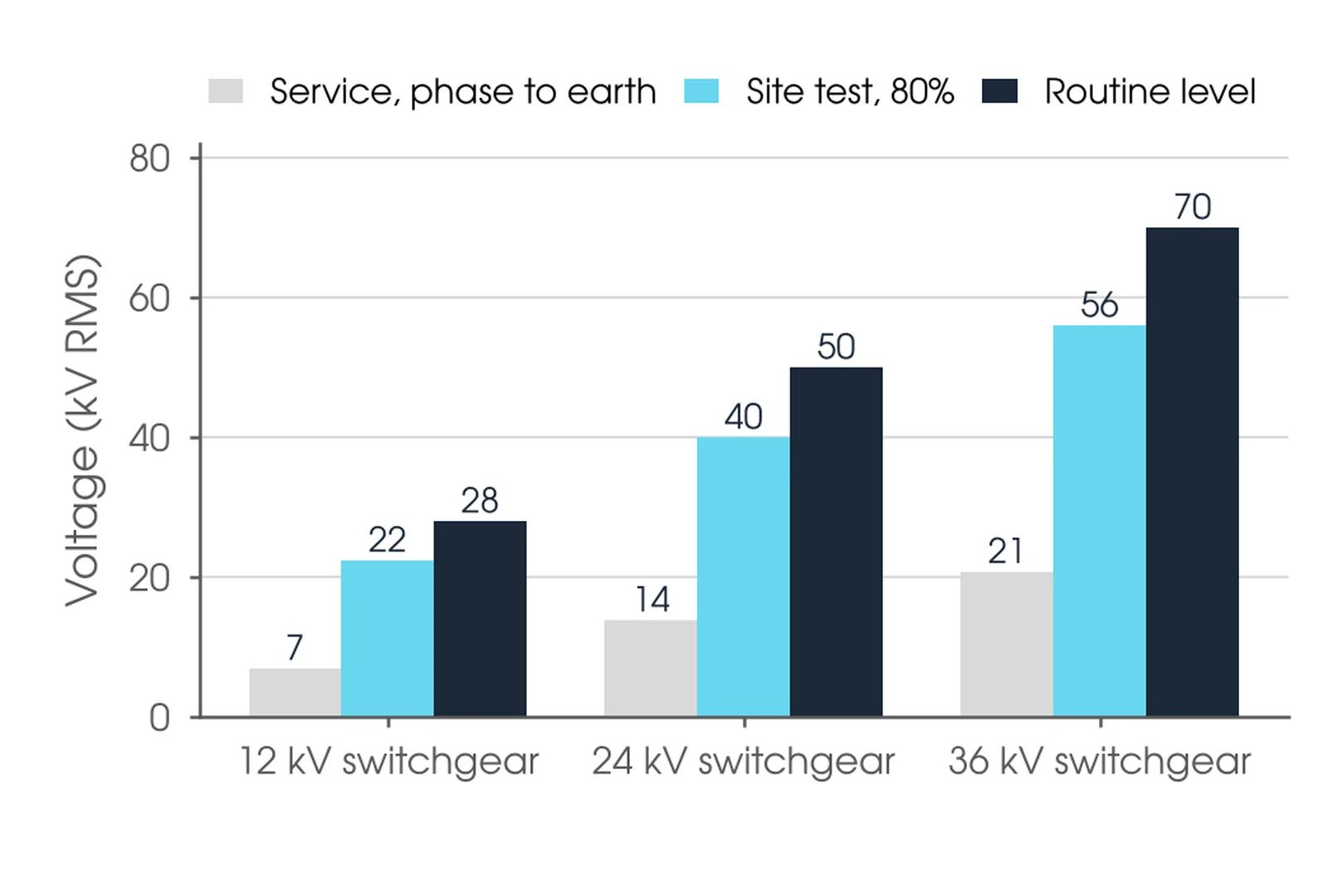
Start from the rating. The routine power-frequency withstand value Ud comes from the rated voltage and insulation level: 28 kV for 12 kV switchgear, 50 kV for 24 kV and 70 kV for 36 kV (AS 62271.1:2019, Table 1). On site, parts of metal-enclosed switchgear from 1 kV to 52 kV that were assembled or filled on site are tested at 80% of that routine value, each phase in turn with the others earthed (AS/NZS 62271.200:2026, 8.104 a)). Routine tests not done in the factory are done in full on site. For 24 kV switchgear that is 0.8 × 50 = 40 kV.
Equipment that has been in service is tested lower again: bushings at 85% of the Table 3 values (AS/NZS 60137:2020, 7.1) and instrument transformers at 80% with a minimum of Um (AS 61869.1:2024, 7.3.1). A transformer repaired to restore function is tested at 80% to 100% of the original level, with new parts at 100% (AS/NZS 60076.3:2017 Amd 1, clause 8). Our recommendation is to take the level from the equipment standard and the manufacturer's site test schedule and agree it with the asset owner before the outage (AS 2067:2016, 9.4). Resolve any conflict between the owner's specification, the standard and the manufacturer in the approved test plan before applying voltage. For a worked example on a power transformer, see hipot testing a 25 MVA power transformer.
Why not repeat the full factory level? The 80% condition check level reflects the insulation co-ordination margin for ageing, wear and normal deterioration, and the statistical nature of flashover (AS 62271.1:2019, 7.2.12 Note). Why not go lower? A lower level proves less than the standard asks, and on-site tolerances and measuring uncertainty are already larger than in the factory (IEC 60060-3:2006, clause 1, Note 2). Record the level in kV and as a percentage of the rated value, with the clause it came from.
How does a hipot test work?
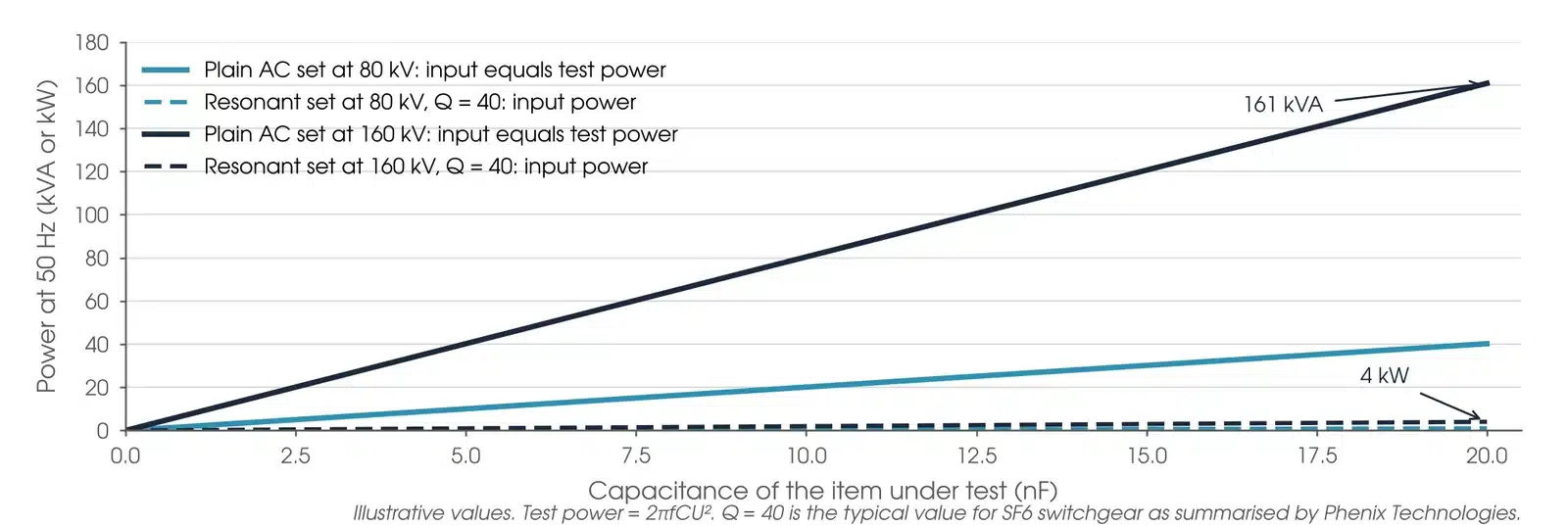
The voltage comes from one of three sources. An AC test transformer steps up a regulated supply; without reactive compensation its input equals the test kVA (as summarised by Phenix Technologies), so it suits low-capacitance items. A resonant set tunes an adjustable reactor against the capacitance of the item, by inductance or frequency, so the supply only provides the losses. A DC set charges the item and then supplies only leakage and absorption current; its test value is the arithmetic mean, with ripple not more than 3% (AS/NZS IEC 60060.1:2026, clause 5).
In a series resonant circuit, a discharge in the item detunes the circuit and the follow-through current is low, so there is generally less damage to the item (AS/NZS IEC 60060.1:2026, 6.1.2.3). Parallel resonant operation gives a steadier voltage on unstable items and full voltage with no load, while series operation suits partial discharge measurement and releases less energy on failure (as summarised by Phenix Technologies).
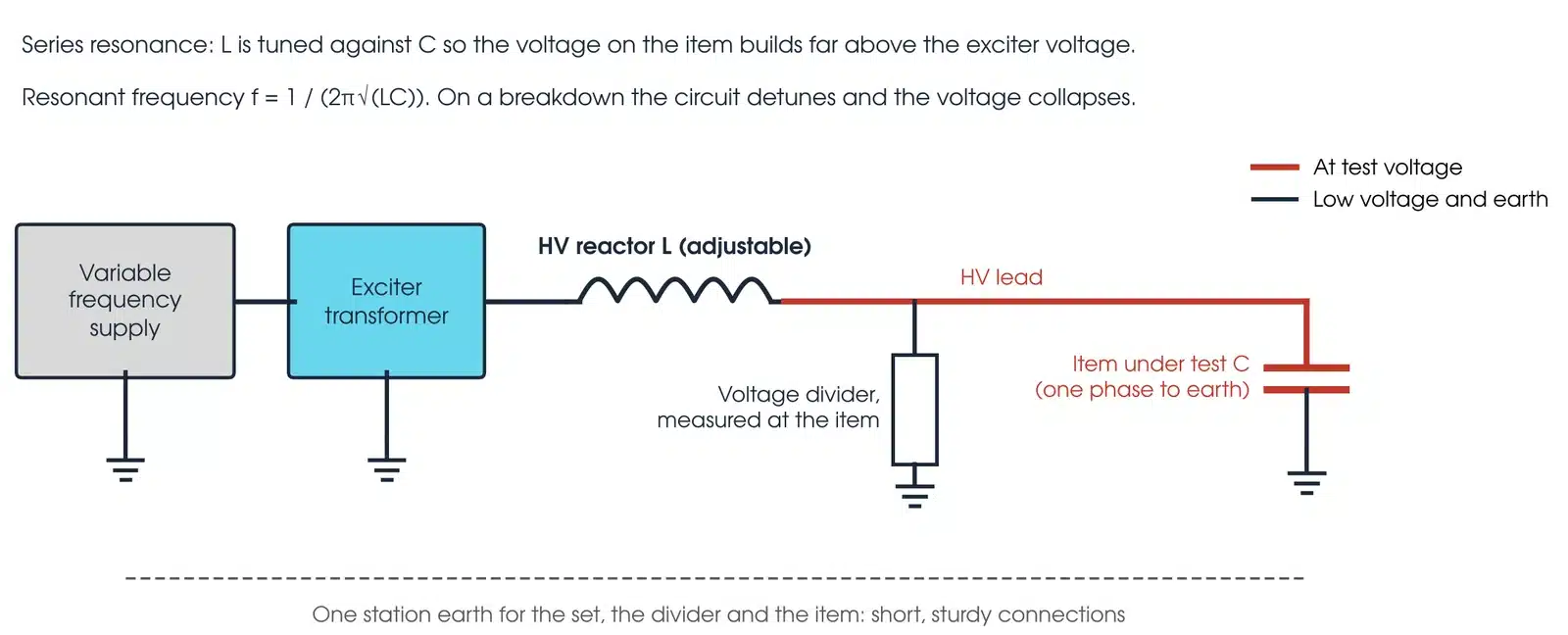
The AC test value is the peak divided by √2 (AS/NZS IEC 60060.1:2026, 3.7). On site the frequency is generally 10 Hz to 500 Hz; above 75% of the test voltage it is raised at about 2% of U per second, held for 60 s if no other time is specified, and kept within 3% of the specified level, or 5% for longer tests (IEC 60060-3:2006, 6.3.1, 6.3.2 and 6.6). The voltage is measured with the item in the circuit, after an on-site performance check of the measuring system (4.3). AC, DC and other waveforms do not necessarily stress insulation equally (clause 1, Note 1), so use the waveform the equipment standard names.
What is the difference between a hipot test and an insulation resistance test?
They answer different questions. An insulation resistance test applies a modest DC voltage, measures resistance and trends the condition of the insulation over time. A hipot test applies an overvoltage for a set time and gives pass or fail. The two work together: run the insulation resistance test first to pre-qualify the insulation (as summarised by Megger, 2021), then repeat it after the hipot and compare. Insulation resistance testing has its own guide in this series.
How do I set up a hipot test safely?
The test puts HV on the item and on everything connected to it, including remote cable ends. Four steps come before any HV lead is connected:
- Confirm the access permit covers everything the test energises, including remote ends, and any temporary removal of earths by the person the asset owner authorises.
- Confirm the plant is isolated and proved dead, and that each HV exposed part is earthed after it is de-energised (Safe Work Australia model Code of Practice: Managing Electrical Risks in the Workplace, 4.1).
- Set barriers and signs around the test set, the item and every remote end. Exclusion zones and permits are administrative controls under the Code (2.3).
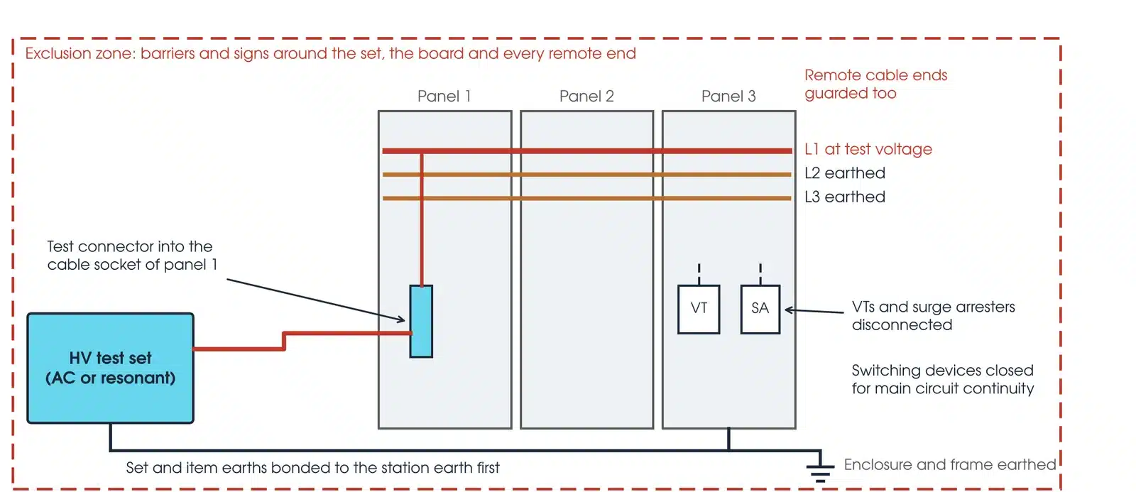
- Bond the test set and the item to the station earth before any HV lead, with short, sturdy connections (IEC 60060-3:2006, 5.4.5).
Only competent workers trained in HV electrical work carry out the test (Code of Practice, chapter 9), under the asset owner's safety rules. The item stays charged after the test, DC most of all: discharge it through the test set's resistor and then earth it solidly. For machine windings USBR FIST 3-1 recommends at least 1 hour earthed.
How is a switchboard set up for a hipot test?
One phase is connected to the test set, often through a test connector in the cable socket, with the other two phases and the enclosure earthed and the switching devices closed so the whole main circuit is tested (AS/NZS 62271.200:2026, 8.2). VTs are disconnected unless the test frequency is high enough to prevent core saturation, and overvoltage protective devices such as surge arresters are disconnected (8.2 and 8.104 a)). Gas-insulated compartments are tested at the specified gas pressure, after filling and gas quality checks (AS 62271.1:2019, 8.2; AS/NZS 62271.4:2026, 4.2). Keep extraneous structures at least 1.5 times the shortest discharge path away (AS/NZS IEC 60060.1:2026, 4.2).
This guide describes general practice for competent HV testing personnel. It is not a work procedure. Work under the asset owner's safety rules, the access permit and a site-specific safe work method statement. Manufacturer and asset owner criteria take precedence over the general guidance here.
How do you perform a hipot test?

- Prepare. Confirm the agreed level, duration and waveform. Check the measuring system scale factor on site (IEC 60060-3:2006, 4.3).
- Insulation resistance. Run an insulation resistance test first to pre-qualify the insulation. A poor reading stops the hipot.
- Connect one phase. HV lead to one phase; the other phases and the enclosure earthed; switching devices closed for continuity.
- Clear the zone. Everyone outside the barriers, remote ends guarded, and the test supervisor confirms before energising.
- Ramp up. Start low and raise at about 2% of U per second above 75% of U (IEC 60060-3:2006, 6.6).
- Hold. Hold for the specified time, 60 s if none is given. Watch the voltage and the current.
- Lower and discharge. Reduce rapidly but do not interrupt suddenly, which can cause switching transients (IEC 60060-3:2006, 6.6). Discharge and earth the phase.
- Recheck and restore. Repeat the insulation resistance test, then test the next phase. Restore earths, VTs and arresters per the permit.
Record which phase was energised and which were earthed for every result.
What are the common hipot testing mistakes?
| Mistake | What it does |
|---|---|
| VT left connected | Core saturation at power frequency and possible damage (AS/NZS 62271.200:2026, 8.104 a)) |
| Surge arrester left in | It conducts, the set trips and the test is invalid |
| Gas below the specified pressure | The insulation is not tested in its rated condition |
| Level not taken from the nameplate | The wrong row of the table is used and the test proves the wrong thing |
| Switching off at full voltage | Switching transients can cause damage or erratic results (IEC 60060-3:2006, 6.6) |
| Long or thin earth leads | Voltage differences if a flashover occurs (IEC 60060-3:2006, 5.4.5) |
| AC test straight after a DC test | USBR FIST 3-1 allows about 2 hours for absorption charge to dissipate first |
How do I read a hipot test result?
The result is pass or fail: the item passes if no disruptive discharge occurs (AS/NZS IEC 60060.1:2026, clauses 5 and 6; AS 62271.1:2019, 7.2.5 a)). The insulation resistance readings either side of the test add the detail. A phase can pass the withstand and still need attention.
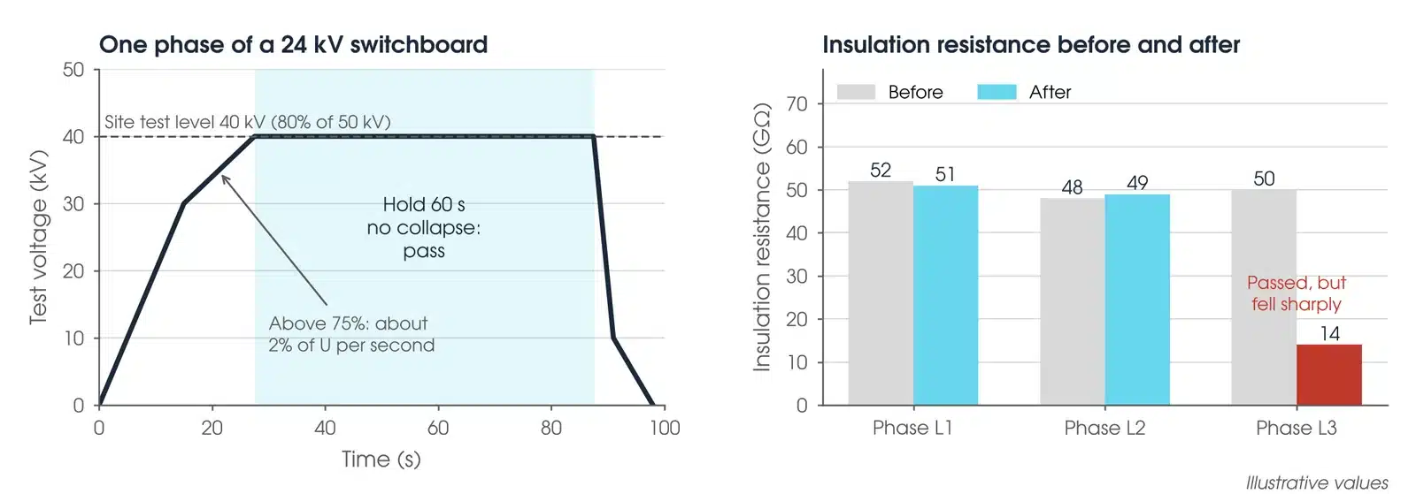
Some insulation is allowed a second chance. In a wet test, one discharge on external self-restoring insulation allows a repeat (AS 62271.1:2019, 7.2.5 a)); a bushing flashover allows one repeat only, and puncture of a capacitance graded bushing is assumed if its capacitance after the test rises by about the capacitance of one layer (AS/NZS 60137:2020, 9.4.3). Compare insulation resistance before and after, phase to phase and with the last test. A fall after a pass is a finding.
What causes a hipot test to fail?
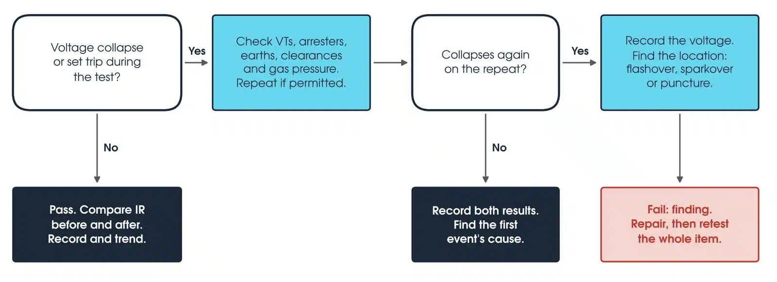
A hipot test fails on a disruptive discharge: the test voltage collapses. AS/NZS IEC 60060.1:2026, 3.1, separates the kinds. Flashover runs along a surface, sparkover goes through gas or liquid, and puncture goes through solid insulation and leaves permanent damage. Causes include damaged, contaminated or wet insulation and particles or protrusions in GIS. A set-up error, such as a VT or surge arrester left connected, can trip the set and look like a failure.
| Pattern | What it usually means |
|---|---|
| Voltage collapses | Disruptive discharge: a fail. Find whether it was flashover, sparkover or puncture |
| Set trips before full voltage | A VT or arrester left in, the wrong item connected, or more capacitance than the set can supply |
| Current rising during the hold | Rising leakage or discharge activity. On DC, an abrupt current increase means stop (USBR FIST 3-1) |
| Hissing, but no collapse | A non-disruptive discharge such as corona (AS/NZS IEC 60060.1:2026, 3.1.6). Measure partial discharge to find it |
| Insulation resistance falls after a pass | A finding. Investigate before energisation |
Is my result OK?
If the voltage held for the full time without collapse, the item passed: compare insulation resistance before and after, record it and trend it. If the voltage collapsed or the set tripped, check VTs, arresters, earths, clearances and gas pressure, and repeat once where the standard permits it, mainly for self-restoring insulation. A repeat that holds does not prove a set-up error: record both results and find the cause of the first event before release. If it collapses again, record the voltage, find whether it was flashover, sparkover or puncture, and report a failure to repair and retest.
How do I work out the site test voltage?
For metal-enclosed switchgear on site, U site = 0.8 × Ud (AS/NZS 62271.200:2026, 8.104 a)). Worked example: a 24 kV switchboard has Ud = 50 kV (AS 62271.1:2019, Table 1), so U site = 0.8 × 50 = 40 kV, held for 60 s on each phase in turn.
To size the source, test power = 2πfCU². A 10 nF item at 40 kV and 50 Hz needs about 5 kVA from a plain AC set; a resonant set supplies only the losses (as summarised by Phenix Technologies).
What should a hipot test report include?
The test voltage with the standard, clause and percentage used; the waveform, frequency and duration; pass or fail, the current at test voltage and insulation resistance before and after for each phase; gas pressure, temperature and humidity, and where atmospheric correction is applied the actual conditions and factors (AS/NZS IEC 60060.1:2026, 4.3.3.1); and the test set and divider serial numbers, calibration dates and the on-site performance check (IEC 60060-3:2006, 4.4).
Which voltage source should I use?
A plain AC test set is simple and works at power frequency, which suits low-capacitance items: switchgear panels, insulators and short bus sections. For high capacitance, such as GIS, long busbars and large bushings, a resonant set draws typically 1/10th to 1/40th of the test kVA, and a typical quality factor for SF6 switchgear is 40 (as summarised by Phenix Technologies).
DC needs only a small set, but it stresses insulation differently from AC. Megger notes that DC at the equivalent peak is normal where capacitance makes an AC test impractical; use it only where the equipment standard or manufacturer allows it. Cable withstand testing uses VLF or resonant AC and is covered in its own guide in this series.
Should partial discharge be measured during a hipot test?
A pass shows the insulation held, not that it is free of defects. Partial discharge measured with the test finds particles, protrusions and voids in GIS (as summarised by OMICRON). For metal-enclosed switchgear, a site PD test is optional. Choose and record the Annex B.3 connection, stating whether each voltage is phase-to-earth or phase-to-phase. Apply its pre-stress voltage for at least 10 s, reduce without interruption to its measuring voltage and measure after 10 s, with acceptance values agreed beforehand (AS/NZS 62271.200:2026, Annex B).
Which hipot test set should I use?
Match the test set to the level and the capacitance of the item. Every set below is available from Megavar.
| Test set | Output | Best used for |
|---|---|---|
| Phenix 6CP50 | 50 kV AC | Withstand tests on MV switchgear, insulators and bushings; portable |
| Phenix BK130 | 130 kV AC | Higher test levels on switchgear, insulators and bushings |
| SUTE 300 kV resonant | 300 kV, 25 to 300 Hz | Capacitive loads such as GIS; reactors in series or parallel |
| Phenix 500 kV resonant | 500 kV, 45 to 300 Hz | Transmission GIS, large bushings and high test levels |
| PFISTERER CONNEX Size 2 | Um 42 kV; 95 kV AC, 5 min | Touch-proof test connection into CONNEX sockets on switchgear |
Every set is supplied with current calibration certificates, safety barriers and earthing leads, with Australia-wide delivery, through Megavar's HV test equipment hire. If you would rather have the test done, Megavar's engineers carry out high voltage testing and substation commissioning across Australia.
Download the hipot testing guide (PDF)
Frequently Asked Questions
What is a hipot test on cables used for?
To prove cable insulation withstands an overvoltage after installation or repair. Cable withstand testing uses VLF or resonant AC to the cable standards and is covered in its own guide in this series.
What is the difference between a megger and a hipot?
A Megger insulation tester measures insulation resistance at a modest DC voltage and trends condition. A hipot applies an overvoltage for a set time and gives pass or fail. The insulation resistance test is run before and after the hipot.
What test voltage should I use on site?
The level from the equipment standard: for metal-enclosed switchgear from 1 kV to 52 kV assembled or filled on site, 80% of the routine power-frequency value (AS/NZS 62271.200:2026, 8.104 a)), agreed with the asset owner.
How long does a hipot test take?
The hold is 60 s unless otherwise specified (AS/NZS IEC 60060.1:2026, clause 6), for each phase in turn, plus set-up and insulation resistance checks before and after.
Can a hipot test damage the insulation?
It can advance existing deterioration even without a failure. The US Bureau of Reclamation (FIST 3-1) advises against the full test voltage on equipment that has been in service, which is why site levels are reduced.
Is AC or DC better for a hipot test?
Use the waveform the equipment standard names. AC, DC and other waveforms do not necessarily stress insulation equally (IEC 60060-3:2006, clause 1, Note 1).
Why use a resonant test set?
A resonant set draws only the circuit losses, typically 1/10th to 1/40th of the test kVA (as summarised by Phenix Technologies), so it can test high-capacitance items such as GIS from a modest supply.
Does Megavar test as well as hire?
Yes. Megavar's engineers carry out HV testing across Australia, and the test sets in this guide are available for hire. Call 1300 730 499.
Need a hipot test done, or the test set to do it?
Megavar carries out HV testing across Australia, and hires every test set in this guide. Call 1300 730 499 or email service@megavar.com.au.