CT testing proves that a current transformer has the ratio and polarity on its nameplate, a healthy magnetic core and sound secondary insulation, and that its secondary circuit will carry the current to the relay or meter as designed. The tests are made from the secondary terminals of the de-energised CT with a low energy test set: ratio, polarity, excitation (knee point) curve, winding resistance, burden and insulation resistance. Primary injection then proves the whole circuit through to the relay. This guide covers each field test, the voltages applied to the secondary, the safety framework around an energised CT and how to judge a result.
Download the CT testing guide (PDF)

What is CT testing?
CT testing is the set of field tests that prove a current transformer is the one the protection and metering were designed around. Every protection and metering decision is made on the CT secondary current. A wrong tap, reversed polarity or a core that saturates early gives the relay a current that is not the one in the primary, so the protection trips when it should not, or fails to trip when it must. The fault is invisible until the day it is needed, unless a test finds it first.
The two failure modes show up in different schemes. A differential or earth fault scheme trips on load when one CT in the group is wrong; a feeder relay under-reaches when its CT saturates. TasNetworks' Secondary Equipment Testing Standard notes that transformer differential protection often reaches the commissioning stage with circuit errors, either in design or wiring.
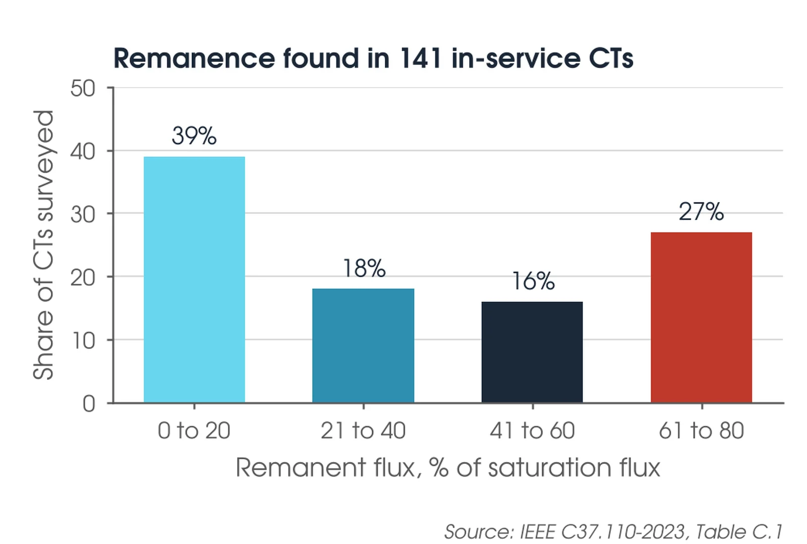
A magnetised core fails early. DC in the primary, or any DC test, leaves remanence in the core, and IEEE C37.110-2023 (clause 4.6.1) shows a C800 CT reaching saturation in 25 ms with no remanence and 5 ms with 75% remanence. The survey in the chart below, from Table C.1 of the same guide, found more than a quarter of in-service CTs holding remanence above 60% of saturation flux. It stays there until the core is demagnetised.
When should a CT be tested?
At the factory, where the routine tests of AS 61869.2 Table 10 set the record; at commissioning, with the full set of tests and primary injection; at the asset owner's routine interval, so the excitation curve can be trended; after any work on the CT or its secondary circuit; and after a heavy through-fault with DC offset, which may have magnetised the core.

Where is CT testing used?
Every CT in a substation is tested at commissioning, from bushing CTs inside transformers and breakers to free-standing HV units and the ring CTs in switchgear. The table gives the common types, what a bad result usually points to and the tests that matter most.
| Current transformer | What a bad result points to | Key tests |
|---|---|---|
| Bushing CTs in transformers and circuit breakers | Wrong tap selected, lead polarity crossed, core magnetised, coupling between cores | Ratio, polarity, excitation on every core and tap in use |
| Free-standing HV CTs, oil or SF6 | Moisture in the main insulation, lowered knee point, shorted turn | Excitation, winding resistance, capacitance and tan delta on the HV insulation |
| Switchgear ring and wound primary CTs | Open or shorted secondary, wrong ratio for the setting, undersized for the burden | Ratio, polarity, burden |
| Metering CTs, classes 0.2S and 0.5S | Burden outside the 25% to 100% band the accuracy class is specified for | Ratio error and phase displacement at the connected burden |
| Protection CTs, classes 5P, 10P, PX and PXR | Knee point e.m.f. or exciting current outside the nameplate value, remanence | Excitation curve, winding resistance, burden |
| Core balance and neutral CTs | Cable sheath earth passed back through the window, polarity reversed | Polarity, primary injection through the window |
How many tests of CT?
Seven in this guide: ratio, polarity, excitation curve, winding resistance, burden, insulation resistance and primary injection. AS 61869.2:2021 defines the CT classes and their limits: ratio error and phase displacement for the measuring classes (Table 201), composite error for 5P and 10P (Table 205), and knee point e.m.f. and exciting current for PX and PXR (clause 5.6.202.4). IEEE C57.13.1-2017 is the field test guide and describes the methods for ratio, polarity, insulation resistance, winding resistance, excitation, admittance and burden (Clause 6). The asset owner's standard sets what is tested and when: TasNetworks requires newly installed CTs to be tested for polarity (clause 12.2) and the ratio of each core proven by primary injection (clause 13.3).
Our recommendation is ratio, polarity, excitation, winding resistance, burden and insulation resistance on every core at commissioning, then primary injection through the complete circuit. The asset owner's specification overrides this.
What voltage is applied to the CT secondary?
For the ratio test the applied voltage stays below the knee point so the core remains linear; OMICRON recommends 50% to 75% of the knee point voltage. The excitation curve has to pass through the knee, so that test goes above it, but only for as long as the readings take (IEEE C57.13.1, clause 12.1). USBR FIST 3-8 limits the exciting current to twice rated secondary current and the secondary voltage to 1,500 V. A test set can reach the same flux at a lower voltage by lowering the frequency, which is how knee points of several kilovolts are measured safely (IEEE C57.13.1, clause 12.2.3). Test the full winding where you can. A tap is compared with the manufacturer's curve and rating for that tap; the IEEE C rating applies to the full winding unless otherwise specified (IEEE C57.13, clause 6.4.2).
How does a CT test work?
Primary ampere-turns supply the secondary ampere-turns plus the core's exciting current. Exciting current causes the ratio and phase errors, and it is small until the core approaches saturation. The excitation test measures it directly: voltage is applied to the secondary with the primary open and the exciting current recorded at each step. Plotted on log-log axes the curve is steep below the knee and nearly flat above it.
There are two knee point definitions, and they give different numbers on the same CT. AS 61869.2 (clause 3.4.215) defines the knee as the voltage where a 10% rise gives 50% more exciting current. IEEE C57.13 (clause 6.10.2) uses the point where the tangent is at 45° on log-log axes. The IEC knee reads about 20% to 25% higher (IEEE C37.110, clause 4.3.2), so name the definition with every value.
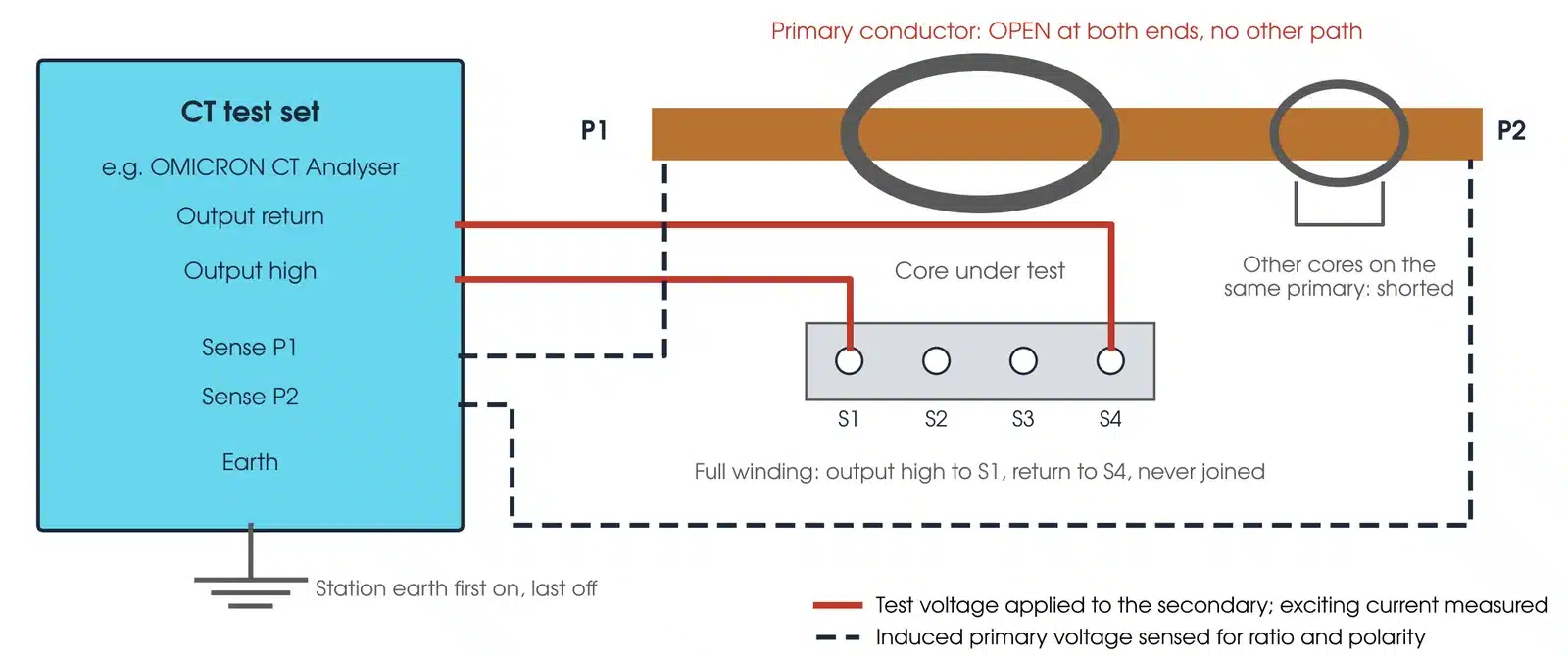
Ratio and polarity come from the same set-up. The voltage induced on the open primary gives the turns ratio, and its phase against the applied voltage gives polarity: near 0° correct, near 180° reversed (IEEE C57.13.1, clause 9.4.2).
Four connection rules follow. The primary conductor must be open-circuited for the excitation test, with no closed loop through the breaker, earth switch or an adjacent CT (IEEE C37.110, clause 4.2). Every other core on the same primary is shorted or left on its burden: OMICRON measured turns ratio errors up to 3.5% on transformer bushing CTs when the windings around them were left open. Demagnetise before the excitation test and after any DC test (IEEE C57.13.1, clause 5.1). And read the voltage with an average-responding meter calibrated in rms, because that is how manufacturers' curves are taken; an rms meter reads more than 10% high above the knee (IEEE C57.13.1, Annex B).
How do I set up a CT test safely?
The tests are low energy, but they are made on plant inside an access permit and on circuits that feed in-service protection. Four steps come before any lead is connected:
- Confirm the access permit covers the work. Work on CTs and their secondary circuits only under the asset owner's safety rules. Revenue metering CTs also need the metering provider (TasNetworks, clause 3.6).
- Confirm at the plant, with the permit issuer, that the primary is isolated, proved dead and earthed. Open the disconnectors before any connection is made to a breaker bushing CT (IEEE C57.13.1, clause 9.4.3).
- Isolate the secondary on a checklist. List every CT link, trip and breaker fail isolation on an alteration and isolation checklist, and restore from the same list (TasNetworks, clause 6.4).
- Connect the test set to the station earth before any other lead, and remove it last.
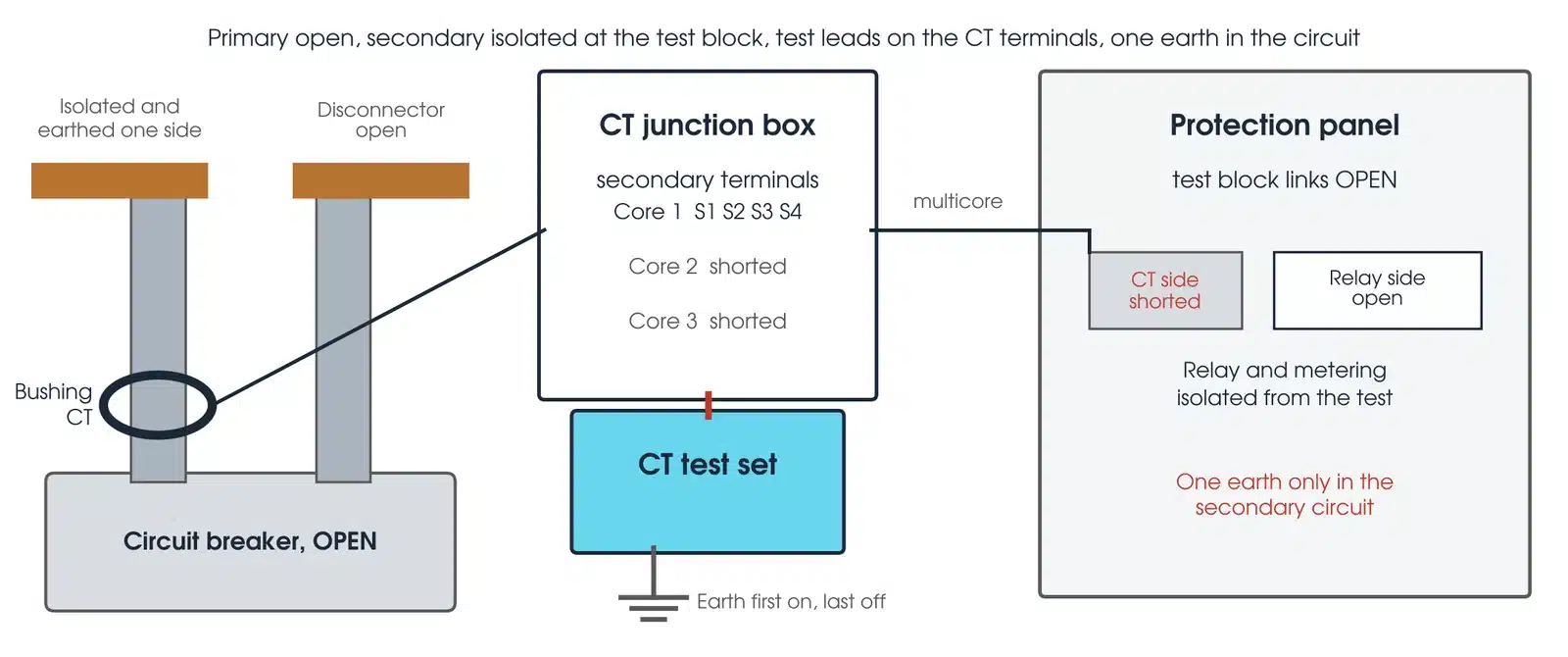
Five hazards are specific to CTs. Never open an energised CT secondary: an open-circuited CT in service, or during injection, develops voltages that can be lethal, damage the insulation and flash over (TasNetworks, clause 3.5), so short the CT side at the test block before the relay side is opened. Most CTs arrive with the secondary shorted; remove the shipping short and connect the secondary loop before the primary is energised (IEEE C57.13.1, Annex A.2.2). DC leaves remanence: a winding resistance or DC polarity test magnetises the core, so demagnetise after any DC test and before returning the CT to service (IEEE C57.13.1, clause 9.1). Breaking a DC source from a CT winding generates a dangerous voltage; parallel a resistor of about the winding resistance across it first (clause 9.1). And keep one earth only in the secondary circuit: a second earth forms a loop with the first, and Doble reports 2.08 A induced through a relay by adjacent lines, which tripped a 161 kV breaker.
The test is for competent, authorised testing personnel working under the asset owner's safety rules; IEEE C57.13.1 (Clause 5) restricts the tests to experienced personnel familiar with the hazards of the set-ups. This guide describes general practice. It is not a work procedure. Work under the asset owner's safety rules, the access permit and a site-specific safe work method statement. Manufacturer and asset owner criteria take precedence over the general guidance here.
How do I make the measurement?

- Isolate and short. With the primary isolated under the permit, short and verify the CT side at the test block before opening the relay and metering side. Remove the circuit earth only for the insulation test, and check for a second earth while it is off (USBR FIST 3-8, clause 5.2).
- Insulation resistance. Secondary winding and circuit to earth at 500 V DC (USBR FIST 3-8, clause 5.3) or 1 kV DC (AS 61869.1, clause 5.4.5.3). Relays stay disconnected unless they are rated for the test voltage.
- Winding resistance. Four-wire DC measurement at the short-circuiting terminal block. Record the temperature; the standard value is corrected to 75 °C (AS 61869.2, clause 7.3.201).
- Demagnetise and excite. Demagnetise, then raise the secondary voltage in steps through the knee, recording the exciting current. Take the readings near the knee closely (IEEE C57.13.1, clause 12.2.1).
- Ratio and polarity. Apply a voltage below the knee to the full winding and read the induced primary voltage and its phase. Check every tap in use against the full winding.
- Burden. Measure the connected burden from the CT terminals with the CT disconnected, at or near rated secondary current, and compare with the nameplate output (IEEE C57.13.1, Clause 15).
- Demagnetise and restore. Demagnetise after the last test. Restore every link from the checklist, replace the circuit earth, then remove the test set earth last.
Run the winding resistance test before the excitation test: the excitation test demagnetises the core afterwards (Doble, 2022).
How to measure CT burden?
Disconnect the CT from the circuit, drive rated secondary current into the connected burden from the CT terminals and measure the voltage needed; volts times amps is the burden in VA, and a phase angle meter gives its resistive and reactive parts (IEEE C57.13.1, Clause 15). Tests at a small fraction of rated current are not conclusive, because the low core flux leaves margin; the most revealing burden tests are made at full rated secondary current (Clause 14). Compare the result with the rated output on the nameplate. TasNetworks checks that metering CTs below class 1 see between 25% and 100% of rated burden, and that protection CTs do not exceed their specified burden at rated current and under worst case conditions (clause 10.4.2).
What are the common CT testing mistakes?
| Mistake | What it does to the result |
|---|---|
| Tap compared with the wrong curve | A tap compared with the full winding curve reads low and looks like a fault; use the curve and rating for that tap |
| Other cores left open | Turns ratio errors up to 3.5% on transformer bushing CTs (OMICRON) |
| Primary loop closed | A closed breaker or earth switch is a shorted turn through the window; the curve collapses |
| Core not demagnetised | After a DC test the curve is distorted and the CT goes back to service magnetised |
| RMS meter above the knee | Reads more than 10% high and triggers an investigation of a healthy CT (IEEE C57.13.1, Annex B) |
| Knee definitions mixed | An IEC knee compared with an IEEE curve shows a 20% to 25% difference that is not real |
| Links not restored from the checklist | A CT left shorted at the test block, or a trip left isolated, when the bay returns to service |
How do I read a CT test result?
A CT result is judged four ways: against the nameplate, against the class limits in AS 61869.2, against the manufacturer's excitation curve, and against the CT's own history. A core can pass its limit and still need attention when it sits far from its sister cores.
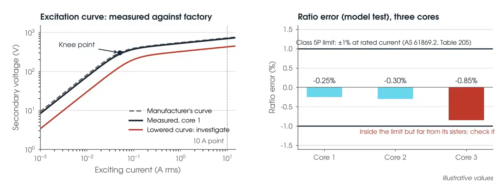
The nameplate gives the ratio, class, rated output or burden, and for PX and PXR the knee point e.m.f. and exciting current. The voltage ratio test verifies the turns ratio, tap and polarity, not the accuracy class (IEEE C57.13.1, clause 6.1). The class limits come from AS 61869.2: class 5P allows ratio error of ±1% and phase displacement of ±60 minutes at rated current and burden, shown by a current test or a validated model-based test with its assumptions recorded, and 10P allows ±3% (Table 205); class 0.5 allows ±0.5% at 100% current (Table 201); PX allows a turns ratio error of 0.25% and PXR 1% (clause 5.6.202.4). Against the factory curve, the exciting current below the knee should be within 125% of the curve value and the voltage above the knee not less than 95% of it (IEEE C57.13-2016, Figure 6), and a C class CT must give more than its class voltage at 10 A exciting current (IEEE C57.13.1, clause 12.3). Over time, a slight lowering of the curve with the same shape is normal; a lowered knee, a dip or a spike is not (clause 12.3).
What does a bad CT test result look like?
| Pattern | What it usually means |
|---|---|
| Ratio out by a whole step | The wrong tap is selected, or the leads are on the wrong terminals |
| Polarity near 180° | S1 and S2 are crossed, or P1 and P2 are. Check the drawing before touching the CT |
| Lowered knee, or exciting current a clean sine wave above the knee | A shorted turn; a clean sine wave is a fully shorted core (IEEE C57.13.1, clause 12.3) |
| Winding resistance high | A bad joint in the CT or the leads. Bushing CTs typically run 2 to 3 mΩ per turn (IEEE C57.13.1, Clause 11) |
| Insulation resistance low | Moisture, most commonly on the terminal board; dry out and retest before dismantling (IEEE C57.13.1, Clause 10) |
| Burden above rating | The CT saturates earlier than the protection study assumed |
Is my result OK?
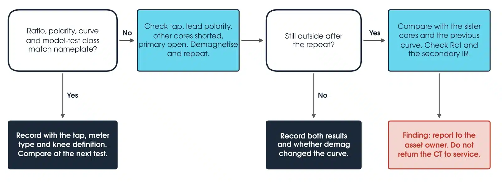
If the ratio, polarity and curve match the nameplate, the class limit and the factory curve, record the result with the tap, meter type and knee point definition used. If not, check the tap, the lead polarity, that the other cores are shorted and the primary is open, demagnetise and repeat. Record both the as-found and repeat results, what was changed and whether demagnetising changed the curve, and identify the cause before calling it a connection error. If it is still out, compare with the sister cores and the previous curve, check the winding resistance and the secondary insulation resistance, and report it as a finding to the asset owner. Do not return the CT to service.
How do I correct winding resistance for temperature?
Secondary winding resistance is specified at 75 °C (AS 61869.2, clause 7.3.201), so correct the measured value before comparing it. With the copper constant 234.5 from IEEE C57.12.90-2021, clause 5.2: R75 = Rt × (234.5 + 75) / (234.5 + T), where Rt is measured at winding temperature T in °C.
Worked example: a 1200/5 core reads 0.610 Ω at 20 °C. At 75 °C it is 0.610 × 309.5 / 254.5 = 0.742 Ω. That 22% rise is temperature alone, and it is the 75 °C value that goes into a PX knee point check.
What should a CT test report include?
For each core and tap: ratio, polarity, knee point voltage and exciting current with the definition used, winding resistance with temperature, burden and insulation resistance. The criteria used: nameplate values, the class limits applied and the manufacturer's curve if one was available. The conditions: test voltage, frequency, meter type, tap connected and whether the CT was demagnetised before and after. And the traceability: test set model, serial number and calibration date, with the signed isolation checklist (TasNetworks, clause 6.2).
What about primary injection?
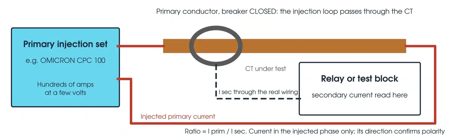
Primary injection passes current through the CT primary and reads it at the relay. The current reaches the relay only if the ratio, polarity, tap, terminal block and multicore are all right, which is why TasNetworks requires it to prove the ratio of each core and the current in each conductor up to the point that overlaps secondary injection (clause 13.3). Secondary tests cannot see a crossed phase, a wrong neutral or two cancelling polarity errors (clause 12.2), and differential and restricted earth fault schemes must be proven by passing current through the transformer and its CTs before energising (clause 13.4).
Primary injection supplies range from 1 kVA to 15 kVA, high current at low voltage (IEEE C57.13.1, Clause 7). On a power transformer the winding impedance limits the current a portable set can drive, so bushing CTs there are tested by the secondary voltage method (OMICRON, 2024).
How to check CT and PT?
For a CT, from the secondary terminals of the isolated unit, then by primary injection through the complete circuit where required, with the relay reading the result. For a VT, use the primary-side method in our VT testing guide; never apply the CT secondary method to a VT. Secondary current times nameplate ratio should equal the injected current, in the phase injected and nowhere else; USBR FIST 3-8 investigates a ratio more than about 3% from the nameplate. Injection at reduced current confirms function; accuracy class is verified only at rated values or by a model-based test (OMICRON, 2025). On a multi-core CT every core carries the injected current at once, so watch shorted circuits and short-time rated relays (TasNetworks, clause 13.2). Read the current at the relay, not the junction box: the point of the test is everything in between.
Which CT test set should I use?
Match the instrument to the test. Every instrument below is available calibrated, with leads, from Megavar.
| Instrument | Method | Best used for |
|---|---|---|
| OMICRON CT Analyser | Secondary injection, model based | Ratio, polarity, excitation, winding resistance and burden, assessed to AS 61869 or IEEE C57.13 |
| OMICRON CT SB2 switch box | Automatic tap switching | Multi-ratio and multi-core CTs in one run |
| OMICRON CPC 100 | Primary injection to 800 A | Primary injection through the circuit to the relay; ratio and polarity |
| OMICRON CPX 200 | Primary and secondary injection | CT and VT ratio in one set |
| OMICRON HVX10 | 10 kV source for the CPX 200 | Tests that need higher voltage on the CPX 200 |
| OMICRON CP TD1 | Tan delta accessory for the CPC 100 | Capacitance and tan delta on the HV insulation of free-standing CTs |
| Megger MIT520 5 kV | Insulation resistance to 5 kV | Secondary winding and circuit insulation resistance |
Every instrument is available from Hobart, Launceston, Adelaide and Newcastle through Megavar's CT testing equipment hire. If you would rather have the test done, Megavar's engineers carry out substation commissioning, protection relay testing and transformer testing from 11 kV distribution to 500 kV transmission.
Download the CT testing guide (PDF)
Frequently Asked Questions
What is CT testing?
A set of field tests that prove a current transformer has its nameplate ratio and polarity, a healthy core and sound insulation, and delivers the right current to its relay or meter.
How many tests of CT?
Seven in this guide: ratio, polarity, excitation curve, winding resistance, burden, insulation resistance and primary injection. IEEE C57.13.1 also describes an admittance test for in-service CTs.
What is CT and PT testing?
The same checks applied to current and voltage (potential) transformers: ratio, polarity, insulation and burden. A VT is tested from its primary side, because its secondary must never be shorted and its primary must never be back-energised.
How to check CT and PT?
For a CT, from the secondary terminals of the isolated unit, then by primary injection through the complete circuit where required, with the relay reading the result. For a VT, use the primary-side method in our VT testing guide; never apply the CT secondary method to a VT.
How to measure CT burden?
Disconnect the CT, drive rated secondary current into the connected circuit from the CT terminals and measure the voltage needed. Volts times amps is the burden in VA (IEEE C57.13.1, Clause 15).
What is the knee point voltage?
The secondary voltage at which the core begins to saturate. AS 61869.2 defines it as the point where 10% more voltage gives 50% more exciting current; IEEE C57.13 uses the 45° tangent on log-log axes.
How often should CTs be tested?
The asset owner's plan sets it. USBR FIST 3-8 gives an excitation test at commissioning and every 6 years, and a burden check after any change to the secondary circuit.
Does Megavar test as well as hire?
Yes. Our engineers commission CTs, VTs and protection schemes across Australia. Call 1300 730 499.
Need CTs tested, or the test set to do it?
Megavar commissions current transformers and protection schemes across Australia, and hires every CT test set in this guide. Call 1300 730 499 or email service@megavar.com.au.