SFRA testing (sweep frequency response analysis) measures how a transformer winding responds to a low-voltage signal swept from 20 Hz to 2 MHz. The result is a trace of amplitude in decibels against frequency that is a fingerprint of the core and winding geometry: move a winding or shift the core and the trace changes. It is also called FRA or frequency response analysis. This guide goes deep on the test itself: the four measurement types, what each frequency band is sensitive to, the lead and earthing rules that make a trace repeatable, safe set-up on the transformer, and how to compare two traces. Where SFRA sits among the other site tests is covered in the transformer testing guide.
Download the SFRA testing guide (PDF)

What is a SFRA test?
A SFRA test is a frequency response measurement on each winding of a power transformer, reactor or similar unit. A low-voltage sinusoid is applied to one terminal with respect to the tank. The voltage at that terminal is the reference (Vin), and the voltage at a second terminal, measured across 50 Ω, is the response (Vout). Amplitude is 20 log10 (Vout / Vin) in dB and phase is the angle between them, recorded at every frequency across the sweep (AS/NZS IEC 60076.18, clause 4.1). The sweep starts at or below 20 Hz and runs to at least 1 MHz above 72.5 kV, 2 MHz at or below it, with 2 MHz recommended for every unit and at least 200 points per decade above 100 Hz (4.5).
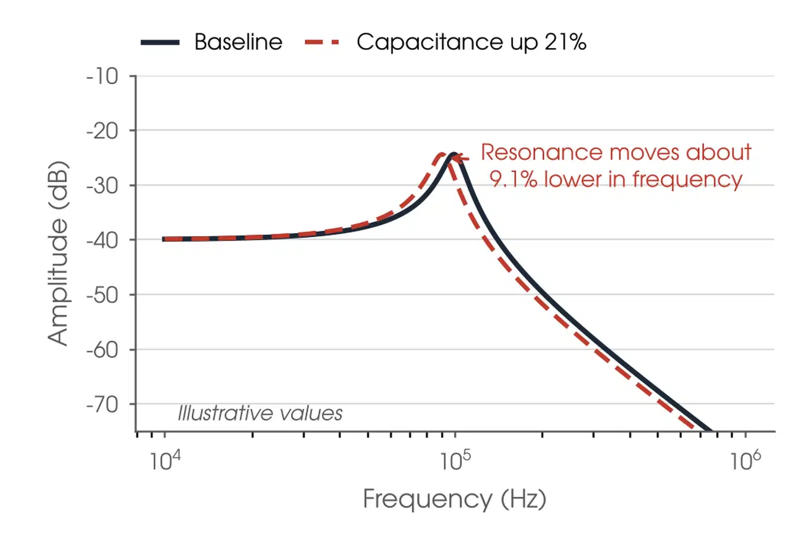
Why it works: every turn of a winding has inductance, and every gap between turns, discs, windings and tank has capacitance. Together they form an RLC network that resonates at frequencies fixed by the geometry. Short-circuit forces from a through fault, shocks in transport, a seismic event or a tap changer fault can buckle, tilt or telescope a winding or shift the core (60076.18, Clause 3). Move the geometry and the resonances move.
A buckled winding does not typically change the ratio or the insulation resistance and is hard to see in capacitance, as summarised by OMICRON. SFRA sees the movement directly, without high voltage, and is the most sensitive electrical test for it. It is a comparison test: the trace is judged against a reference, never read as a single number.
When should an SFRA test be done?
At the factory at the end of the acceptance tests, to set the fingerprint; before transport, as the last electrical test in the transport configuration, and on arrival as the first; at commissioning, assembled and oil filled, as the service baseline; after a through fault, protection trip, Buchholz or gas alarm or seismic event; and when an older, used, spare or relocated unit is assessed (60076.18, Clause 3 and Annex C; IEEE C57.149, 4.1). Detection is most effective with a baseline from the transformer in a known good condition, so the standard prefers a measurement on every large transformer in the factory or at commissioning, or both.

Where is SFRA testing used?
SFRA applies to power transformers, reactors, phase shifting transformers and similar equipment, in the factory and on site, new or in service (60076.18, Clause 1). The standard set of measurements depends on the unit.
| Unit | What a changed trace points to | Standard measurements (AS/NZS IEC 60076.18, 4.4) |
|---|---|---|
| Two-winding three-phase transformer | Radial or axial winding deformation, bulk movement, shorted turns, core shift, loose connections | End-to-end open on each phase of each winding: 6 without taps, 9 with an OLTC |
| Auto-transformer | As above; series, common and tertiary windings separately | 6 without taps, 9 with an OLTC, plus 3 if a tertiary is brought out to three terminals |
| Shunt reactor | Winding movement, core and clamping damage | Treated as a star winding: 3 without taps, 6 with taps |
| Phase shifting transformer | Movement in either core and coil assembly | 18 measurements across neutral and extreme taps |
| Transport check (Annex C.1) | Core, winding and clamping damage in transit | End-to-end open with all other terminals floating, in the transport configuration before and after |
| After a short-circuit test (Annex C.2) | Subtle winding dimension changes not visible by inspection | Baseline at the test station, measurement after; short-circuit sweeps recommended as well |
Which SFRA measurements should I run?
AS/NZS IEC 60076.18:2025 makes the end-to-end open circuit measurement on each phase of each winding the standard measurement, with the phases and windings separated as far as possible and every other terminal floating (4.4.2.1). Inter-winding and short-circuit sweeps are additional, where specified. IEEE C57.149-2024 Table 2 lists fifteen tests for a two-winding transformer and marks tests 1 to 9, the open circuit sweeps on HV and LV plus the HV short-circuit sweeps with the LV shorted, as the recommended minimum; tests 10 to 15 are the capacitive and inductive inter-winding sweeps. Our recommendation is to run the open circuit sweeps on every winding and the short-circuit sweeps on the HV as the standard set, and to repeat any inter-winding sweep that exists in the baseline. The asset owner's specification overrides both.
Which tap position should an SFRA test use?
For a tapped winding with an OLTC, 60076.18 (4.4.2.2) measures on the tap with the most effective turns in circuit and again with the tap winding out of circuit, so damage can be placed in the tap winding or the main winding. IEEE C57.149 (5.8) uses the extreme raise position. Approach a neutral or change-over position from the raise side, and record the previous tap: the position of the change-over selector has a profound effect on the trace. Leave a service-aged unit's DETC on its as-found position and record it; moving a DETC for a test is not recommended by either standard. Split a delta winding with six accessible terminals for the standard sweeps, and keep a tertiary or stabilising delta closed. Where splitting a large generator transformer is impracticable, take agreed open and closed baselines and repeat the matching configuration. Record the terminal state of every neutral and tertiary (60076.18, 4.4.4 and Annex B.4.1).
How does an SFRA test work?
Three coaxial leads are used. The source lead and the reference lead clamp to the same terminal at one end of the winding, and the response lead clamps to the terminal at the other end. The screen of each lead is earthed to the flange at the base of its bushing by the shortest possible braid, pulled tight along the bushing: Method 1 in 60076.18 Annex A, the reference method used for baselines unless agreed otherwise. The leads are 50 Ω coaxial, of equal length, each with attenuation under 0.3 dB at 2 MHz and no longer than 30 m for a passive lead system (5.2).
The four measurement types differ only in what is done with the other terminals (60076.18, 2.6 to 2.9). End-to-end open circuit: everything else floating. End-to-end short circuit: another winding of the same phase shorted. Capacitive inter-winding: source on one winding, response on another, the other ends floating. Inductive inter-winding: as capacitive, but the far ends of both windings earthed.
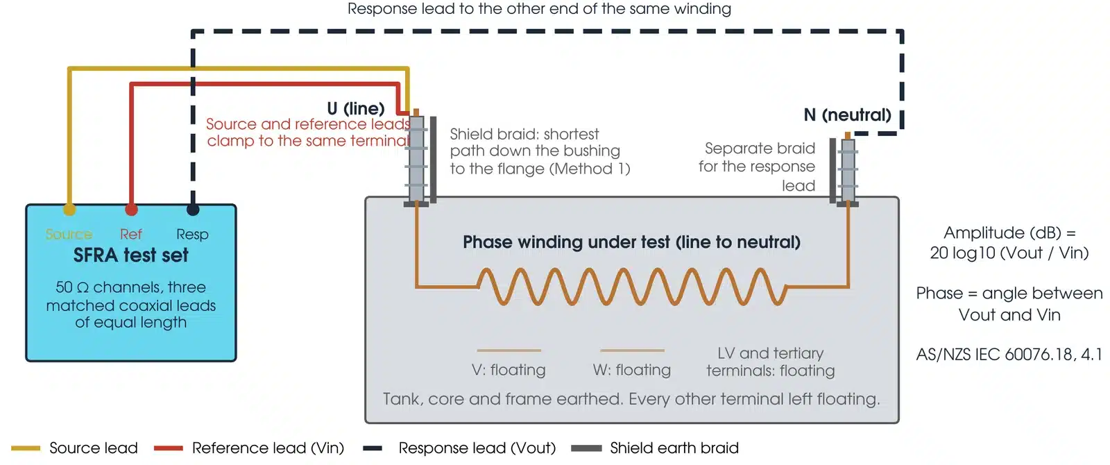
Clean the terminal and the flange to bare metal. A bad contact gives a noisy low-frequency region and a lower amplitude trend (60076.18, B.4.9). Use a flat braid, not a wire: the braid's lower inductance and larger surface suppress noise and give repeatable results above 500 kHz, as summarised by OMICRON.
What is sweep frequency?
Sweep frequency means the test signal is a sinusoid whose frequency is stepped through the range, at least 200 points per decade above 100 Hz and at intervals no wider than 10 Hz below it (60076.18, 4.5), so the response is measured at every frequency rather than derived from one impulse. The standard applies to both swept (SFRA) and impulse (IFRA) sources provided the instrument meets its Clause 5 (2.2).
What does each frequency band of an SFRA trace show?
Up to about 2 kHz the core magnetising inductance and the bulk capacitances dominate, and residual magnetism shows here. From about 2 kHz to 20 kHz the coupling between windings dominates, which depends on the winding arrangement and connections. From about 20 kHz to 1 MHz the winding structure dominates: the leakage inductances with the series and earth capacitances of the winding under test. Above 1 MHz (2 MHz at 72.5 kV and below) the measurement set-up and the earthing connections dominate and the trace is less repeatable. There is no general frequency limit for each region; the limits move with the physical size of the transformer and the ratings of the windings (60076.18, Annex B.3).
How do I set up an SFRA test safely?
The test signal is low voltage, but the test is run on an isolated power transformer inside an access permit, with every terminal disconnected and unearthed while the sweep runs. Four steps come before any lead is connected:
- Confirm the access permit covers the test, including disconnecting every bushing and lifting the terminal earths for the measurement, by the person the asset owner authorises.
- Confirm at the plant, with the permit issuer, that the transformer is isolated, proved dead and earthed: completely isolated from any HV source, tank earthed (IEEE C57.149, 5.2).
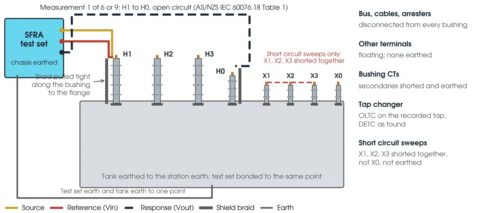
- Disconnect every terminal. Line, neutral and tertiary connections come off every bushing; the tank earth, auxiliaries and CT service connections stay. Bushing CTs not connected to protection: secondaries shorted and earthed (60076.18, 4.2).
- Bond the instrument chassis to the tank earth before any other lead, and remove it last. The tank earth is the reference potential for the measurement (C57.149, 5.4 and 5.6).
Every other terminal is unearthed while the sweep runs, so keep the terminal earths on until the moment of measurement and restore them straight after. Disconnected bushings near live lines or busbars act as antennas (C57.149, 5.6): treat every terminal as live until it is clamped, and record the surroundings with the measurement (60076.18, 6.2). Windings hold charge after insulation tests and energy after a DC winding resistance test, so discharge and earth them before the SFRA leads go on; better, run SFRA first. Refit every bushing test tap cap before the unit is returned to service. Terminals are usually reached from an elevating work platform under the site's working at height rules.
The test is for competent, authorised testing personnel working under the asset owner's safety rules. At Megavar that means assessed testers, with less experienced staff working under direct supervision.
This guide describes general practice for competent HV testing personnel. It is not a work procedure. Work under the asset owner's safety rules, the access permit and a site-specific safe work method statement. Manufacturer and asset owner criteria take precedence over the general guidance here.
How do I make the measurement?

- Prepare and record. Nameplate, vector group, OLTC and DETC positions and the previous tap, oil level and top oil temperature, the state of every neutral and tertiary, and whether a DC test has just magnetised the core (60076.18, Clause 6).
- Connect and check. Clean the terminals and flanges. Clamp source and reference to the first terminal, the response to the other end, and each braid down its bushing. Check the continuity of the main and earth connections at the instrument end of each lead (60076.18, 4.3.1).
- Instrument check. Run the zero check, or the manufacturer's performance check when performance is in doubt: channels joined, 0 dB ±0.3 dB across the range; response open, below -90 dB (60076.18, 4.3.4).
- Open circuit sweeps. Each phase of each winding, line to neutral or in the head-to-tail order of Table 1 or Table 2, at or below 20 Hz up to 2 MHz with at least 200 points per decade (60076.18, 4.4 and 4.5).
- Short circuit sweeps. HV end to end with X1, X2 and X3 shorted together, not earthed and not including the neutral (C57.149, Table 2 note a). Braided copper shorting leads are sufficient.
- Repeatability check. Take the leads and braids off, reconnect and repeat the first measurement. It shows the frequency range that can be relied on under the day's conditions (60076.18, 4.3.3).
- Save and restore. Save every sweep as XML with the Clause 6 record and photographs of the connections. Restore the terminal earths, then remove the test set earth last. Demagnetise if a DC test follows.
Run SFRA before winding resistance, or demagnetise the core first: a DC test shifts the core resonance and spoils the comparison (IEEE C57.152, 7.2.7; 60076.18, B.4.6).
What are the common SFRA testing mistakes?
| Mistake | What it does to the trace |
|---|---|
| Long or coiled earth lead | A loop or a wire instead of a tight braid changes the trace above about 500 kHz, and worse connections push the effect lower (C57.149, 5.5 and 5.6) |
| Braid touching the terminal | Shorts the measurement to earth at the clamp and distorts the high frequencies (as summarised by OMICRON). Use an insulated cover on the braid |
| SFRA after winding resistance | Residual magnetism moves the core resonance to the right and the low-frequency region no longer matches the baseline |
| Different tap position | A changed OLTC or DETC position alters the trace across a wide range, on other windings as well as the tapped one (as summarised by Doble) |
| Bus or arresters still connected | Adds capacitance and inductance the baseline did not have. If a bus must stay, test the same way every time and record it (C57.149, 5.3) |
| Tertiary or neutral in a different state | An open, closed, floating or earthed tertiary, or joined neutrals, changes the interaction region. Match the baseline and record it (60076.18, B.4.1 and B.4.2) |
| Measured in the other direction | Neutral to line instead of line to neutral shows differences at higher frequencies (60076.18, B.4.4) |
| Extra winding earths | Earths added under local rules on windings not under test give a unique trace that cannot be compared with one taken without them (C57.149, 5.5) |
How to read a SFRA graph?
Overlay the current trace on the reference, in dB against log frequency, and look for three things: a change in the overall shape, a change in the number of resonances and anti-resonances, or a shift in the resonant frequencies (60076.18, Annex B.2). The most significant indicator is a resonance gained or lost, then a shift of an existing one; a trace that rises above the original with the same shape as frequency rises points to winding looseness (IEEE C57.149, 7.2). For winding geometry the most useful range is typically about 2 kHz to 1 MHz (2 MHz at 72.5 kV and below), set for the unit and the demonstrated repeatable range; assess the core region below it separately for core and remanence effects. Above it the leads and earthing dominate (60076.18, B.3).
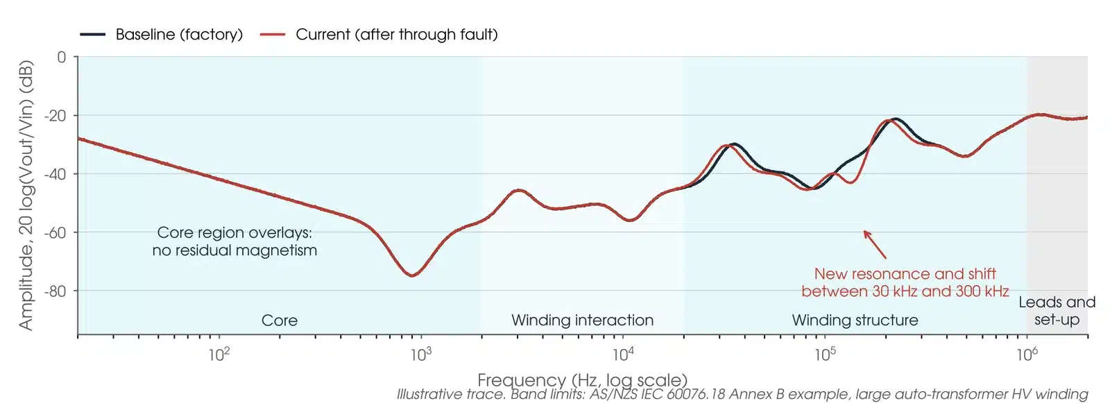
Which reference comes first matters. The unit's own baseline in the same configuration is preferred, then a twin made to the same drawings, then a sister unit of the same specification, then the other phases of the same unit. Sister units can carry design changes that look like damage, and quite significant differences between phases are normal (60076.18, B.2). On the short-circuit sweeps, the three phases should agree within ±0.2 dB in the low-frequency inductive roll-off; outside that, investigate for radial deformation (C57.149, Table 5).
What is SC and OC test?
The open circuit (OC) test is the end-to-end sweep on one winding with everything else floating: the core magnetising inductance shapes the low-frequency region, so it sees the core as well as the winding, and it complements the single-phase exciting current test (C57.149, 5.7.1 and 7.4.1). The short circuit (SC) test repeats it with the other winding shorted, which removes the core from the measurement and leaves the winding impedance: its low-frequency region relates to leakage reactance and, below about 30 Hz, to DC winding resistance (5.7.2, 7.4.3 and 7.4.4). Short-circuit sweeps are not sensitive to core problems, which is why the transport check must include the open circuit sweep (60076.18, Annex C.1).
What does a bad SFRA result look like?
| Pattern | What it usually means |
|---|---|
| New or lost resonance, 20 kHz to 1 MHz | Winding deformation. Radial buckling of an inner LV winding shows most clearly here (C57.149, Table 5) |
| New peaks or valleys, 5 to 100 kHz | Bulk movement of a winding relative to the others; axial telescoping also shows most clearly here (C57.149, Tables 6 and 7) |
| Open circuit trace looks like short circuit | The core reluctance has gone from the measurement: shorted turns, or a core defect if the core resonance shape has changed (C57.149, Tables 8 and 9) |
| Core resonance moved right, nothing else | Residual magnetism from a DC test or switching, not a fault. Demagnetise and repeat (C57.149, 7.5.6) |
| Noisy low frequencies, trace lower overall | A bad contact or loose connection (60076.18, B.4.9). Differences only above 500 kHz are usually the leads and braids |
Is my result OK?
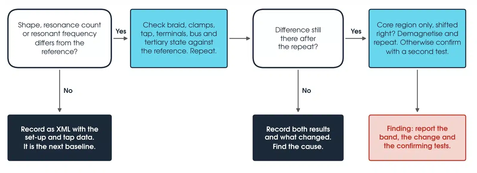
If the shape, the number of resonances or a resonant frequency differs from the reference, check the braids, clamps, tap position, terminal states, bus connection and tertiary state against the reference record and repeat the sweep. If the repeat overlays, record both results and what changed, and find the cause before treating the first trace as a set-up error. If the difference is still there and it is only the core region shifted to the right, demagnetise and repeat. Otherwise confirm with a second test and report it as a finding, naming the band, the change and the confirming tests.
What does the decibel scale on an SFRA trace mean?
The amplitude axis is a ratio, not a voltage: amplitude in dB = 20 × log10 (Vout / Vin) (60076.18, clause 4.1). So -20 dB means the response is one tenth of the reference, -40 dB one hundredth and -60 dB one thousandth. A difference of 6 dB between two traces is a factor of two in the ratio; 3 dB is a factor of 1.41.
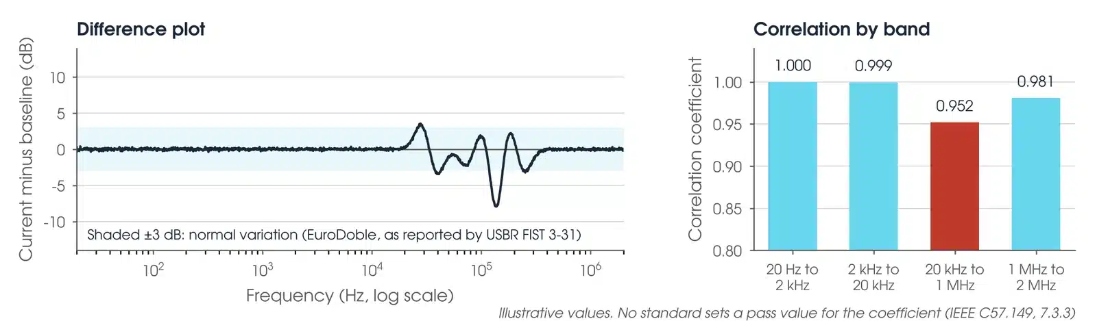
Worked example: a baseline reads -46.0 dB at 85 kHz and the current trace reads -43.0 dB at the same frequency. The response has risen by a factor of 10^(3/20) = 1.41. USBR FIST 3-31 reports changes under 3 dB as normal; treat 3 dB or more as a change to explain, and a resonance that has moved as more significant than one that has changed height.
What should an SFRA test report include?
For every sweep: the reference and response terminals, terminals shorted and earthed, OLTC tap and previous tap, DETC position, peak test voltage, oil temperature and whether the unit was oil filled (60076.18, 6.1). For the set-up: the connection method, braid and lead lengths, core magnetisation state, bus or busbar connected, surroundings such as live lines nearby, and photographs of the connections (6.2). For the comparison: which reference was used, the band in which the traces differ and the criterion met. For traceability: instrument make, model and serial number, calibration date and measuring impedance, with the data saved as XML so it can be read without the instrument software in 20 years (C57.149, 6.2.1).
How do I compare two SFRA traces?
Three methods are used, usually together. The overlay, both traces on one plot in dB against log frequency, is the most common and needs an experienced eye (C57.149, 7.3.1); a linear frequency axis helps when studying one band (60076.18, B.1). The difference plot subtracts one amplitude trace from the other, and any region away from zero needs explaining; it is not applied to phase (7.3.2). The correlation coefficient is the Pearson coefficient of the two amplitude traces, from -1 to 1 with 1 identical, calculated for the whole sweep or band by band (7.3.3); instrument software reports it automatically.
Neither standard sets a pass value for the coefficient, and 60076.18 keeps interpretation in an informative annex. The number supports a judgement; it does not replace one. If the traces differ, repeat the measurement and compare the set-up with the reference before calling a fault (60076.18, B.4.11). Good agreement above 1 MHz between two traces that differ lower down makes a lead or earthing error unlikely, but does not rule out a setup or configuration difference (60076.18, B.4).
A finding is confirmed with a second test that sees the same fault. A change in the short-circuit low-frequency region is checked with a leakage reactance test, and a short-circuit response that is flat below 30 Hz is checked with DC winding resistance (C57.149, 7.4). SFRA and leakage reactance are the two mechanical integrity tests and confirm each other, as summarised by OMICRON.
Which SFRA test set should I use?
Both SFRA sets below meet IEC 60076-18 and IEEE C57.149; the companion sets run the tests that confirm an SFRA finding and demagnetise the core before the sweep. Every instrument is available calibrated, with leads, from Megavar.
| Instrument | Measurements | Best used for |
|---|---|---|
| OMICRON FRANEO 800 | SFRA: open, short circuit, capacitive and inductive inter-winding | Baselines and diagnostics to IEC 60076-18 Method 1, with overlay against the fingerprint |
| OMICRON FRAnalyzer | SFRA: end-to-end, end-to-neutral, cross-phase | Compact SFRA set for site and factory |
| OMICRON TESTRANO 600 | Winding resistance, ratio, short-circuit impedance, demagnetisation | Confirming a finding; demagnetising before the sweep |
| OMICRON CPX 200 | Ratio, winding resistance, excitation, demagnetisation | Compact companion set for the confirming tests |
| OMICRON CPC 100 | Winding resistance, short-circuit impedance, excitation | Leakage reactance and winding resistance |
Every instrument is available from Hobart, Launceston, Adelaide and Newcastle through Megavar's transformer test equipment hire. If you would rather have the test done, Megavar's engineers carry out transformer testing, factory acceptance testing and substation commissioning across Australia.
Download the SFRA testing guide (PDF)
Frequently Asked Questions
What is a SFRA test?
A sweep frequency response analysis: a low-voltage signal swept from 20 Hz to 2 MHz through a transformer winding, recorded as amplitude in dB and phase against frequency, and compared with a reference trace to find winding or core movement.
How to read a SFRA graph?
Overlay the current trace on the reference. Look for a changed shape, a resonance gained or lost, or a resonance moved. Below about 2 kHz is the core, 2 to 20 kHz the winding interaction, 20 kHz to 1 MHz the winding structure, and above 1 MHz the leads.
What is sweep frequency?
The test signal is a sinusoid whose frequency is stepped through the range, at least 200 points per decade above 100 Hz, so the response is measured at every frequency rather than from one impulse.
What is SC and OC test?
The open circuit (OC) sweep is end to end on one winding with everything else floating and shows the core and the winding. The short circuit (SC) sweep repeats it with the other winding shorted, which removes the core and shows the winding alone.
Can SFRA be done without a baseline?
Yes, with care. Compare with a twin or sister unit, or between the phases of the same unit; the centre phase of a three-limb core normally differs at low frequency. The result is less certain than a baseline comparison.
Why is SFRA done before winding resistance?
A DC winding resistance test leaves the core magnetised, which moves the core resonance. Run SFRA first, or demagnetise the core before it (IEEE C57.152, 7.2.7).
Does the test voltage matter?
Only in the core region of an open circuit sweep, where the magnetising inductance depends on the signal level (as summarised by OMICRON). Record the peak voltage and use the same one next time.
Does Megavar test as well as hire?
Yes. Megavar tests power transformers from 11 kV distribution class to 500 kV transmission class, with SFRA compared against the factory baseline. Call 1300 730 499.
Need an SFRA test done, or the instrument to do it?
Megavar tests power transformers across Australia, and hires every SFRA set in this guide. Call 1300 730 499 or email service@megavar.com.au.