VT testing proves that a voltage transformer delivers a secondary voltage that is a true, correctly phased image of the primary voltage, and that its insulation and secondary circuit are fit for service. A test set applies a known voltage to one winding and measures the other; a capacitor stack is measured with a tan delta set. The test is also called potential transformer or PT testing. This guide covers inductive VTs and capacitive voltage transformers (CVTs): ratio and polarity, phase displacement, insulation resistance, tan delta and capacitance, secondary burden, the safety framework and how to judge a result.
Download the VT testing guide (PDF)

What is VT in testing?
In HV work, VT testing means testing a voltage transformer: proving its ratio and polarity, its phase displacement, its insulation resistance, the capacitance and tan delta of its insulation or capacitor stack, and the burden on its secondary circuit. In non-destructive testing the same two letters mean visual testing, which is unrelated to this guide.
Why test a voltage transformer?
A VT feeds protection, revenue metering, synchronising and control at the same time, so a ratio or phase error is copied into every one of them, and a reversed polarity turns a directional or distance element the wrong way. A relay test injects into the relay, not through the VT: a crossed phase, a wrong tap or a shorted turn passes a secondary injection test and fails in service.
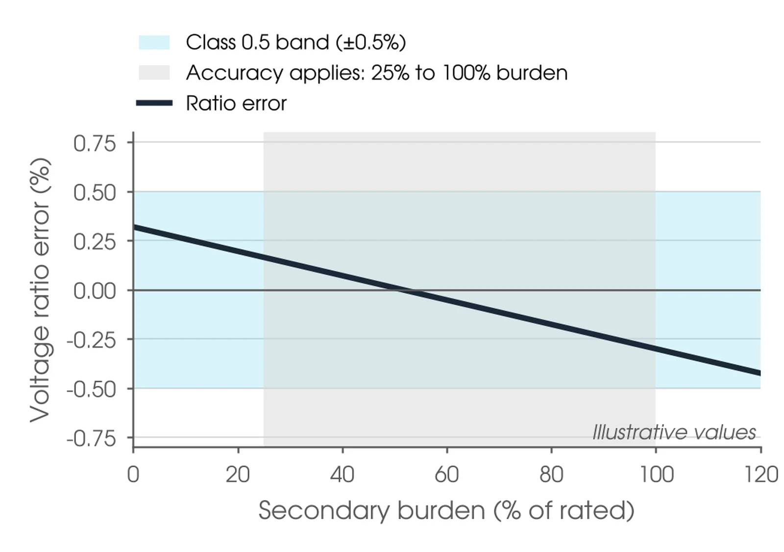
Some faults stay hidden until the unit fails. Shorted capacitor layers in a CVT stack and shorted turns in an inductive VT are often undetected, and some end in a complete breakdown (OMICRON). The connected burden moves the error too: a class 0.5 VT must hold its error inside ±0.5% from 25% to 100% of rated burden for burden range II (AS 61869.3, 5.6.301), so the burden is measured as part of the test.
When should a VT be tested?
At the factory, where the routine withstand, partial discharge and accuracy tests go on the certificate (AS 61869.3, 7.3); at commissioning, where ratio, polarity, insulation resistance and burden are proven before any protection or metering scheme is energised; at the asset owner's routine interval, with CVT capacitance and tan delta trended; after secondary wiring changes or a VT replacement; and after a misoperation, a system fault or ferroresonance.

Where is VT testing used?
Inductive and capacitive voltage transformers at every voltage level, and the secondary circuits they supply. The items below are the common ones, with what a bad result usually points to and the site tests that find it.
| Item | What a bad result points to | Site tests |
|---|---|---|
| Single-phase inductive VT, earthed (A-N) | Wrong ratio or tap, shorted turns, reversed polarity, moisture in oil-paper insulation | Ratio and polarity, IR, tan delta above 72.5 kV |
| Unearthed (phase-to-phase) VT | As above; the insulation of both primary terminals must be checked, each in turn | Ratio and polarity, IR, tan delta |
| Three-phase VT, usually 36 kV and below | Phase markings not matching the primary, wrong category of burden connection | Ratio per phase, phasing, burden (AS 61869.3, Appendix ZA) |
| CVT capacitor stack (C1, C2) | Shorted capacitor layers, moisture: capacitance up, tan delta up | Capacitance and tan delta of C1 and C2 |
| CVT electromagnetic unit | Intermediate transformer or compensating reactor fault, ferroresonance damage | Ratio through the stack at 2 kV, IR |
| Residual voltage (open-delta) winding | Reversed polarity on one phase: a false residual voltage, or none under an earth fault | Polarity on all three phases, burden |
| Secondary circuit | Short circuit, second earth, over-burden or excessive lead drop | IR, burden and voltage drop, single-point earth |
What test voltage should a VT test use?
A site ratio check does not need rated voltage. Site test sets apply from a few hundred volts to 2 kV, which gives the ratio and polarity without a high voltage source in the yard, and OMICRON notes that such a check is a functional test, generally not comparable with the accuracy tests in the standard. AS 61869.3:2021 type tests measuring accuracy at 80%, 100% and 120% of rated voltage (7.2.6.301) and protective accuracy at 2%, 5%, 100% and the rated voltage factor times rated voltage (7.2.6.302), at 25% and 100% of rated burden for burden range II (Table 305). Protective classes are specified down to 5% of rated voltage, and at 2% the limits double (Table 302), so a low voltage check cannot stand in for the factory accuracy test.
The upper limit is the rating. For a CVT ratio test, typically at 2 kV, and for tan delta, typically at 10 kV, the test voltage must not exceed the line-to-earth rating of the unit, and the C2 measurement is held to 500 V where the carrier terminal rating is unknown (OMICRON). Secondary winding insulation resistance is measured at 1 kV DC, or 500 V DC where the secondary withstand rating is below 1 kV (AS 61869.1:2024, 5.4.5.3). A repeat withstand test on a VT that has been in service is at 80% of the rated value, with a minimum of Um (AS 61869.1, 7.3.1).
Our recommendation at commissioning is insulation resistance, ratio and polarity on every winding and tap, burden and voltage drop, and capacitance and tan delta on every CVT and on oil-paper VTs above 72.5 kV. The asset owner's testing standard sets the rest. Record the test voltage, the winding tested, the tap and the burden with every result, and repeat future tests at the same voltage and connection, or the results cannot be compared.
How does a VT ratio test work?
The VT is a step-down transformer. A known voltage is applied to one winding and the voltage on the other is measured; the ratio is U1/U2 and the turns ratio n1/n2 (OMICRON). The secondary is open-circuited for the ratio test unless the ratio under burden is wanted. Accuracy is stated as a voltage (ratio) error in percent and a phase displacement in minutes between the secondary and primary phasors (AS 61869.3, Tables 301 and 302); IEEE C57.13 expresses the same thing as a ratio correction factor, RCF = 1 minus the ratio error divided by 100 (clause 5.2).
Apply the source to the high-turn winding. Energising the secondary induces the full ratio times the applied voltage on the primary (USBR FIST 3-8). A sinusoidal voltage applied to one side and compared as a phasor with the other gives polarity and ratio in one test (OMICRON); a DC kick test with a battery also works but can generate a dangerous voltage when the battery is disconnected (USBR FIST 3-8).
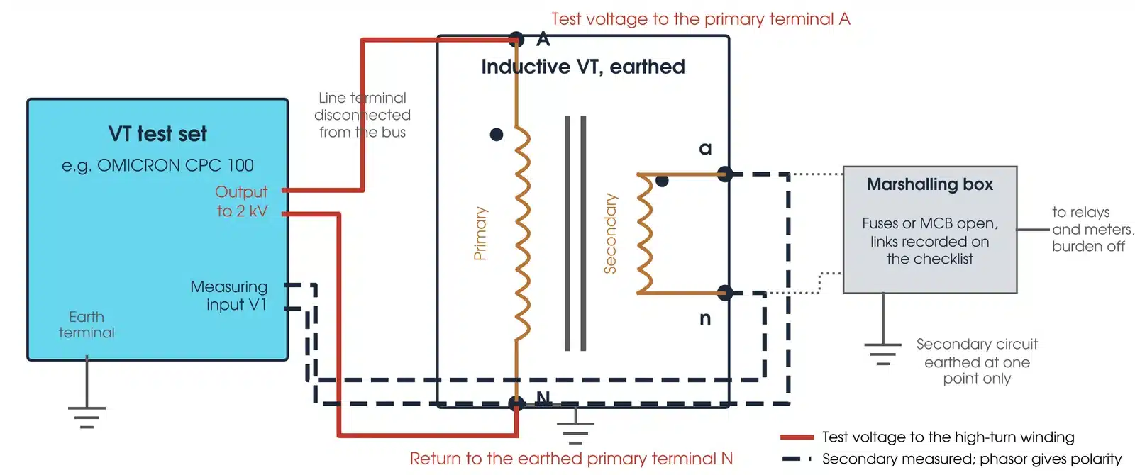
Three connection rules follow. Capital A, B, C and N are primary terminals; lower case a, b, c and n are the corresponding secondaries, and da-dn the residual voltage winding; terminals with corresponding capital and lower case markings have the same polarity at the same instant (AS 61869.3, 6.13.301), and IEEE practice marks them H1 and X1 (IEEE C57.13, 4.9). Earth one terminal of each secondary winding during the test and leave the rest floating (OMICRON); in service the secondary circuit is earthed at one point only (USBR FIST 3-8, 5.2). On a CVT the ratio is measured through the capacitor stack with the potential earth switch open and the carrier earth switch closed, typically at 2 kV (OMICRON), and the capacitive ratio and the intermediate transformer ratio are measured separately to tell a divider fault from an electromagnetic fault.
Are voltage transformers and potential transformers the same?
Yes. Potential transformer, or PT, is the IEEE term (IEEE C57.13); voltage transformer, or VT, is the IEC and Australian term (AS 61869.3). The tests, the terminal conventions and the accuracy ideas are the same; only the names and the class tables differ. Shorted turns change the winding resistance, so a DC winding resistance check on the secondary adds a second view of the winding; demagnetise the core afterwards (OMICRON).
How do I set up a VT test safely?
The test voltages are low, but the VT sits on HV plant inside an access permit and the secondary feeds in-service relays and meters. Four steps come before any lead is connected:
- Confirm the permit covers the VT, the primary disconnection and any temporary removal of earths by the person the asset owner authorises.
- Confirm at the plant, with the permit issuer, that it is isolated, proved dead and earthed. Earth every accessible primary terminal to discharge stored energy, then disconnect the line terminal from the bus (OMICRON).
- Open the secondary fuses, MCBs or links at the marshalling box and at the panel, and record each isolation on the alteration and isolation checklist (TasNetworks). Tell the metering provider before touching a metering circuit.
- Bond the test set and the VT base to the station earth before any other lead, and remove that bond last.
Four hazards are specific to VTs. A VT is a step-up transformer in reverse: injecting into a secondary that is still connected can energise the primary, and the bus or line, at full voltage through the VT secondary (TasNetworks), so prove the primary isolated and the secondary circuit open before any secondary injection. A short circuit applied to the secondary of an energised VT drives a damaging current through the winding, so prove there is no short before livening and set test meters to volts before touching a live secondary (TasNetworks). Capacitor stacks hold charge after de-energisation and after every test: earth the stack terminals to discharge it before connecting and before touching any lead (OMICRON). And never exceed the line-to-earth rating of the unit; keep the CVT C2 test to 500 V where the carrier terminal rating is unknown, and barricade every terminal that will be energised (OMICRON).
The test is for qualified and competent personnel (AS 2067, cl 2.1.1) working under the asset owner's safety rules. At Megavar that means assessed testers, with less experienced staff working under direct supervision.
This guide describes general practice for competent HV testing personnel. It is not a work procedure. Work under the asset owner's safety rules, the access permit and a site-specific safe work method statement. Manufacturer and asset owner criteria take precedence over the general guidance here.
How do I make the measurement?

- Isolate and discharge. Primary disconnected and earthed, secondary circuit open at the fuses or links, CVT stack discharged. Remove the primary earth only when the test needs it.
- Nameplate and wiring. Ratio, class, burden, voltage factor and terminal markings against the drawings; confirm the VT sits where the circuit diagram says it does and that secondary equipment ratings match it (TasNetworks, 8.4).
- Insulation resistance. Each secondary winding to earth and to the other windings at 1 kV DC, or 500 V DC where the secondary withstand is below 1 kV, held until the reading settles and for at least 30 s (AS 61869.1, 7.4.5). Primary to earth at the voltage the previous test used.
- Ratio and polarity. Energise the primary and measure every secondary winding and tap. Compare the ratio with the nameplate and the polarity with the markings. On a three-phase VT, confirm the secondary phase markings against the primary first (TasNetworks, 12.3).
- Capacitance and tan delta. On a CVT: C1 and C2 in series, then C2 at 500 V with the carrier earth switch open, then C1 at 10 kV; on an oil-paper VT above 72.5 kV, the primary insulation at the approved field voltage, compared with the factory reference measured at that voltage, with the ambient temperature recorded (OMICRON; AS 61869.1, 7.3.10). Discharge the stack between every measurement.
- Burden and voltage drop. Disconnect the VT winding from the circuit and prove it isolated, then inject into the burden wiring only. Measure the current per phase to calculate the connected burden, and the voltage drop out to the device supplied (TasNetworks, 10.4.1).
- Restore and prove phasing. Restore every isolation from the checklist. After livening, confirm phasing against a known VT, check phase rotation at the VT terminals and measure the on-load burden against the injected value (TasNetworks, 15.3).
What are the common VT testing mistakes?
| Mistake | What it does |
|---|---|
| Secondary circuit not isolated | The test energises the relays and meters, or the whole bus through the VT |
| Source applied to the secondary | Full primary voltage on the open primary terminal (USBR FIST 3-8) |
| Burden left connected | The ratio reads low and is not comparable with the nameplate |
| Second earth on the secondary circuit | Circulating current under fault, and the IR test earths itself (USBR FIST 3-8) |
| CVT earth switches in the wrong position | Potential switch closed during the ratio test gives no ratio; carrier switch open leaves the HF terminal floating (OMICRON) |
| Damp or dirty porcelain | Surface leakage makes the tan delta and IR readings meaningless. Clean and dry the housing first (OMICRON) |
| Test voltage not recorded | The next test cannot be compared, and a tan delta at 10 kV is compared with a limit set at Um/√3 (AS 61869.1, 7.3.10) |
How do I read a VT test result?
A VT result is judged against the accuracy class, the nameplate, the factory certificate, the other phases or sister units, and the VT's own history. A result inside the class that has moved away from its factory value still needs attention.
What is an acceptable VT ratio error?
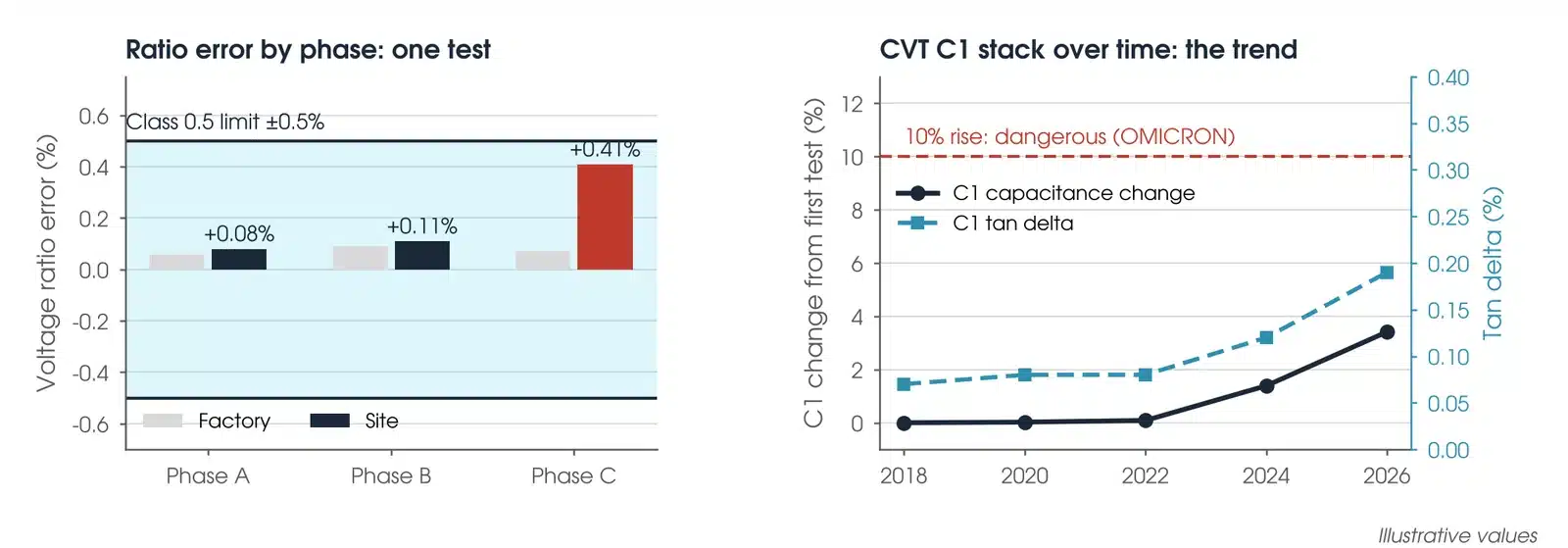
The accuracy class on the nameplate. Measuring classes allow 0.1 to 1.0 percent voltage error with 5 to 40 minutes phase displacement, and class 3.0 has no phase limit (AS 61869.3, Table 301). Protective classes 3P and 6P allow ±3% and ±120 minutes, and ±6% and ±240 minutes, from 5% of rated voltage to the voltage factor (Table 302). A low-voltage site check is a functional test and does not show class conformity; it is compared with the factory certificate and the other phases as well: OMICRON's CVT examples show capacitance within about 0.1% to 0.7% of the nameplate and ratio within about 0.4%.
For a CVT stack, a capacitance rise of more than 10% against previous results is normally considered dangerous, because part of the stack is shorted and the rest is overstressed (OMICRON). For oil-impregnated paper the tan delta limit is 0.005 at Um/√3 and ambient temperature (AS 61869.1, Table 5); a 10 kV site reading is compared with the factory 10 kV value, not with that limit (7.3.10). Secondary insulation resistance is 200 MΩ or more at 1 kV DC where requested, noting that site humidity can lower the reading (AS 61869.1, 5.4.5.3); USBR FIST 3-8 expects much more than 1 MΩ on a secondary circuit at 500 V and investigates anything below it. Burden sits within 25% to 100% of rated output for range II burdens (AS 61869.3, 5.6.301); TasNetworks sets the same range where the nameplate does not, and limits the secondary lead drop to 0.2 V for metering and 2.5 V for protection (10.4.1).
What does a bad VT test result look like?
| Pattern | What it usually means |
|---|---|
| Ratio out on one winding | Wrong tap, wrong nameplate reading or shorted turns. Check the tap and the winding resistance before condemning the VT |
| Polarity reversed | Leads crossed at the test set, the marshalling box or the VT. Trace the wiring; a reversed residual winding gives a false residual voltage |
| Capacitance up, tan delta up | Shorted layers or moisture in the stack. Compare C1 and C2 separately and with the other phases |
| Ratio right, capacitance wrong | Both C1 and C2 have shifted together, or the electromagnetic unit is compensating. Measure the capacitive and inductive ratios separately (OMICRON) |
| Low or unstable insulation resistance | Moisture, damp porcelain or a second earth on the secondary circuit |
| Burden below 25% of rated | Identify the burden range first: range I includes zero burden, range II normally covers 25% to 100% (AS 61869.3, 5.5). Add a burden only where the design requires it, rated and checked for every winding; TasNetworks suggests about 50% of rated output |
Is my result OK?
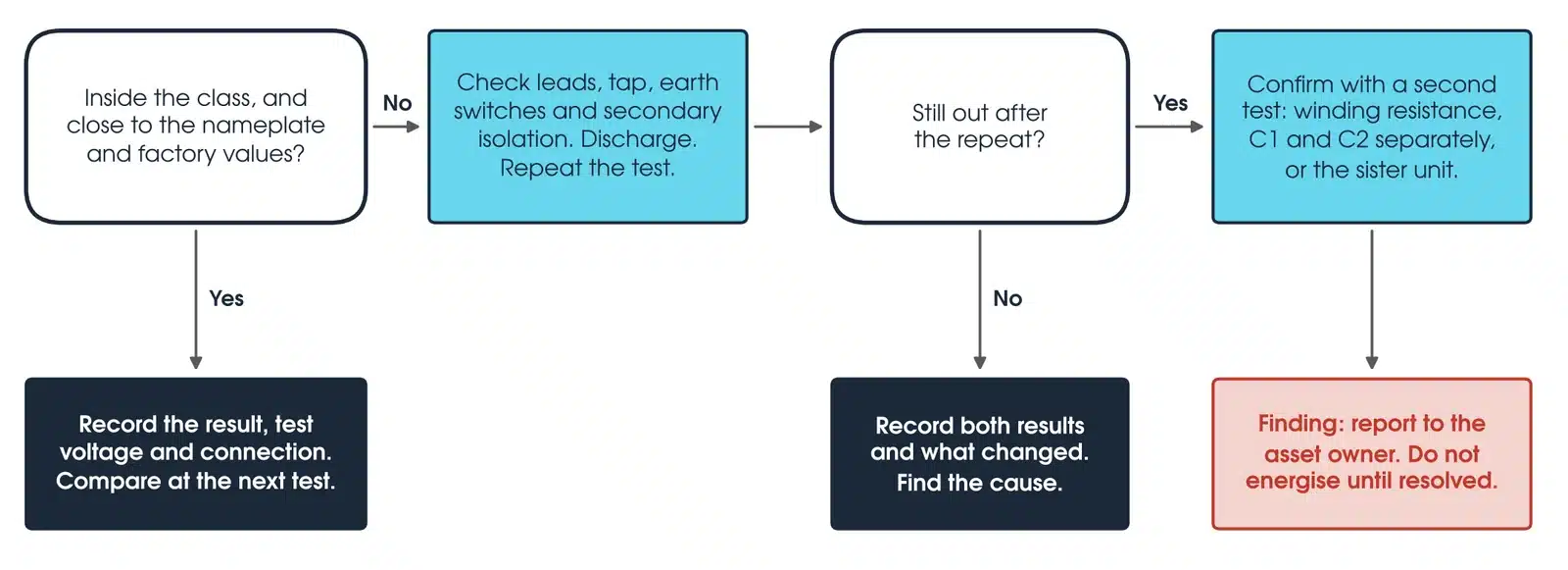
If the result is inside the class and close to the nameplate and factory values, record it with the test voltage and connection and compare at the next test. If not, check the leads, the tap, the CVT earth switches and the secondary isolation, discharge, and repeat. A repeat that reads normally does not prove a connection error: record both results and what changed, and find the cause. A repeat that is still out is confirmed with a second test, such as winding resistance, C1 and C2 measured separately, or the sister unit, and reported to the asset owner as a finding. The VT is not energised until it is resolved.
How do I calculate VT ratio error and phase displacement?
IEEE C57.13 (clause 5.2) relates the ratio correction factor, the ratio error and the phase angle γ in minutes through the transformer correction factor: RCF = 1 − (±ratio error / 100), and TCF = RCF + γ / 2600, where RCF is the true ratio divided by the marked ratio. Phase displacement in radians × 3438 gives minutes (IEEE C57.13, 10.1.2).
Worked example: a 66 kV/√3 : 110 V/√3 VT, marked ratio 600, is energised at 2,000 V and reads 3.3447 V on the secondary. The measured ratio is 597.96, so RCF is 0.9966 and the ratio error is +0.34%. With a phase displacement of 12 minutes, TCF is 1.0012. At about 5% of rated voltage and without rated burden this is a functional check: it does not show class 0.5 conformity (AS 61869.3, 5.6.301). Compare it with a reference measured at the same voltage.
What should a VT test report include?
The nameplate and conditions: ratio, class, burden, voltage factor, serial number, ambient temperature and humidity, and the time since de-energisation. Every result: each winding and tap with applied voltage, measured voltage, ratio, ratio error, polarity and phase displacement; insulation resistance by winding; capacitance and tan delta by stack unit. The comparison against the class, the nameplate, the factory certificate, the other phases and the previous test. And traceability: instrument models, serial numbers and calibration dates, the earth switch positions used, and the signed alteration and isolation checklist (TasNetworks).
What is a capacitive voltage transformer (CVT)?
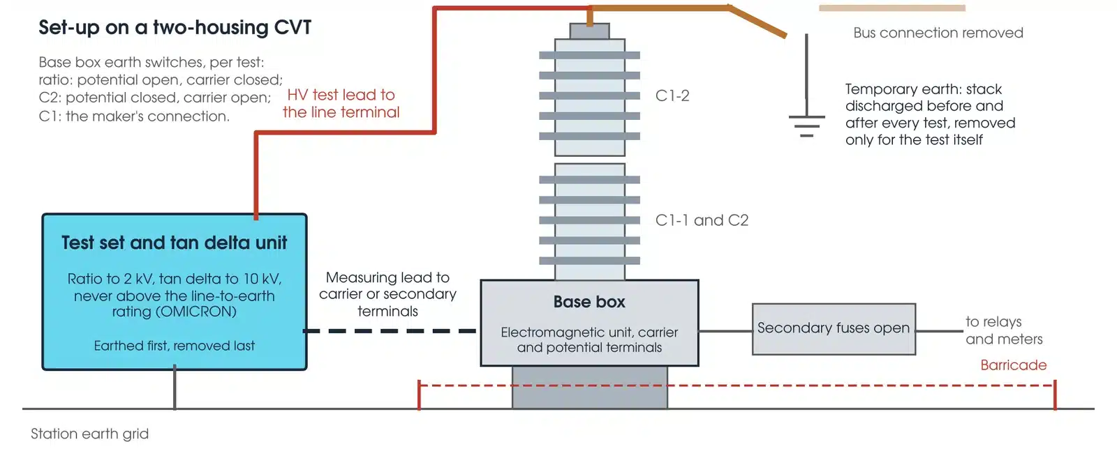
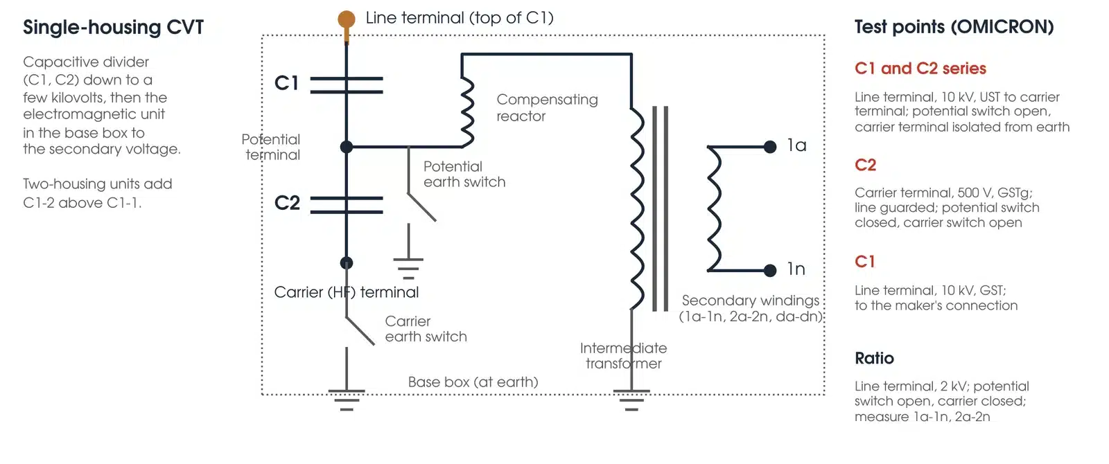
A capacitive voltage transformer is a VT for transmission voltages that uses a capacitor stack to divide the line voltage to a few kilovolts, then an intermediate inductive transformer to bring it to the secondary voltage. The capacitors sit in one or more housings, C1 above C2; a two-housing unit has C1-2, C1-1 and C2. In the base box a compensating reactor and the intermediate transformer bring the tapped voltage to the secondary, beside the carrier (HF) terminal and, where accessible, the potential terminal (OMICRON).
The capacitance and the intermediate transformer form a circuit that can ferroresonate. In an inductive VT, residual voltage windings damp relaxation oscillations (AS 61869.3, 3.1.308); a CVT has its manufacturer's own damping circuit. Damping resistors or de-tuning are the remedies AS 60071.2 (5.3.2.4) names. A CVT that has ferroresonated is tested before it returns to service.
How is a CVT tested?
Three tan delta measurements and a ratio test (OMICRON). C1 and C2 in series as the overall test at up to 10 kV, with the potential earth switch open and the carrier terminal isolated from earth; then C2 alone from the carrier terminal at 500 V, with the potential earth switch closed, the carrier earth switch open and the line terminal guarded; and C1 alone at 10 kV to the manufacturer's connection (Megger). Each capacitance is compared with the stack nameplate. The ratio is then measured through the stack with the potential switch open and the carrier switch closed, 2 kV on the line terminal and each secondary winding measured. A ratio check alone often misses shorted capacitor layers; the capacitance measurement finds them.
Which VT test set should I use?
Match the instrument to the test. Every instrument below is available calibrated, with leads, from Megavar.
| Instrument | Test | Best used for |
|---|---|---|
| OMICRON CPC 100 | Ratio and polarity to 2 kV | VT and CVT ratio, polarity and burden; automated VT test plans |
| OMICRON CP TD1 | Tan delta and capacitance to 12 kV | CVT stacks and oil-paper VT insulation, with the CPC 100 |
| OMICRON CPX 200 | Ratio, polarity, winding resistance | Compact multi-function VT and CT testing with integrated demagnetisation |
| OMICRON HVX10 | 10 kV AC and DC source | Tan delta, capacitance and insulation resistance with the CPX 200 in one set-up |
| Megger MIT1020 10 kV | Insulation resistance to 10 kV, PI and DAR | Primary insulation of transmission VTs |
| Megger MIT520 5 kV | Insulation resistance to 5 kV | Secondary windings at 500 V or 1 kV, and distribution VTs |
Every instrument is available from Hobart, Launceston, Adelaide and Newcastle through Megavar's voltage transformer test equipment hire. If you would rather have the test done, Megavar's engineers test VTs and CVTs as part of protection relay testing and substation commissioning across Australia.
Download the VT testing guide (PDF)
Frequently Asked Questions
What is VT in testing?
In HV work, VT testing is the testing of a voltage transformer: ratio, polarity, insulation, tan delta and burden. In non-destructive testing the same letters mean visual testing, which is unrelated.
Are voltage transformers and potential transformers the same?
Yes. Potential transformer, or PT, is the IEEE term (IEEE C57.13); voltage transformer, or VT, is the IEC and Australian term (AS 61869.3). The tests are the same.
What is a capacitive voltage transformer (CVT)?
A VT for transmission voltages that uses a capacitor stack to divide the line voltage to a few kilovolts, then an intermediate inductive transformer in the base box to bring it to the secondary voltage.
What is an acceptable VT ratio error?
The accuracy class on the nameplate: for example ±0.5% and ±20 minutes for class 0.5, or ±3% and ±120 minutes for class 3P (AS 61869.3, Tables 301 and 302). A low-voltage site check is functional only: compare it with the factory value.
What insulation resistance should a VT secondary have?
AS 61869.1 (5.4.5.3) gives 200 MΩ or more at 1 kV DC where requested. USBR FIST 3-8 investigates any secondary circuit reading below 1 MΩ at 500 V.
Can I inject into the VT secondary?
For ratio and polarity, use the primary-side method. Inject a burden circuit only with the VT winding disconnected and proved isolated; a connected secondary can back-energise the primary at full voltage (TasNetworks).
How often should VTs be tested?
The asset owner's plan sets it. USBR FIST 3-8 verifies secondary earthing and insulation resistance at commissioning, after wiring changes and at least every 6 years. CVT stacks are trended on a multi-year cycle.
Does Megavar test as well as hire?
Yes. Megavar tests VTs and CVTs with every protection and commissioning scope, from 11 kV distribution to 500 kV transmission. Call 1300 730 499.
Need VTs tested, or the instruments to do it?
Megavar tests voltage transformers and CVTs with every protection and commissioning scope across Australia, and hires every instrument in this guide. Call 1300 730 499 or email service@megavar.com.au.