Secondary isolation separates the protection, control and metering circuits under test from the circuits that stay in service. It is made at links, test blocks and terminals in the panel, and in relay software, so that a test cannot reach plant in service and plant in service cannot reach the tester. This guide sets out the principles behind it: why a CT is shorted before it is opened, why a VT is never shorted, why trip circuits open first and close last, how work areas are delineated, and the checks before restoration. It is not a procedure. The network operator's or site's access and safety rules govern every secondary isolation.
Download the secondary isolation guide (PDF)

Why does secondary isolation matter?
A wrong isolation, or a wrong restoration, does one of three things. It trips plant in service: a trip, breaker fail or intertrip left connected lets a test trip a live breaker or another bay. It leaves plant unprotected: a CT short or an isolation left on after the work returns the bay to service with a scheme that cannot see a fault. Or it exposes a person to a dangerous voltage.
A second earth can trip plant too. A 2024 Doble conference paper reports 161 kV breakers opened when CT secondaries were shorted and earthed at the CT for an insulation test: the new earth formed a loop with the panel earth, and the loop picked up current induced by adjacent lines. IEEE C57.13.1-2017 (Annex A.1) warns that removing a CT circuit earth with the primary energised can produce dangerous voltages by electrostatic coupling.
Why is a CT shorted before it is opened?
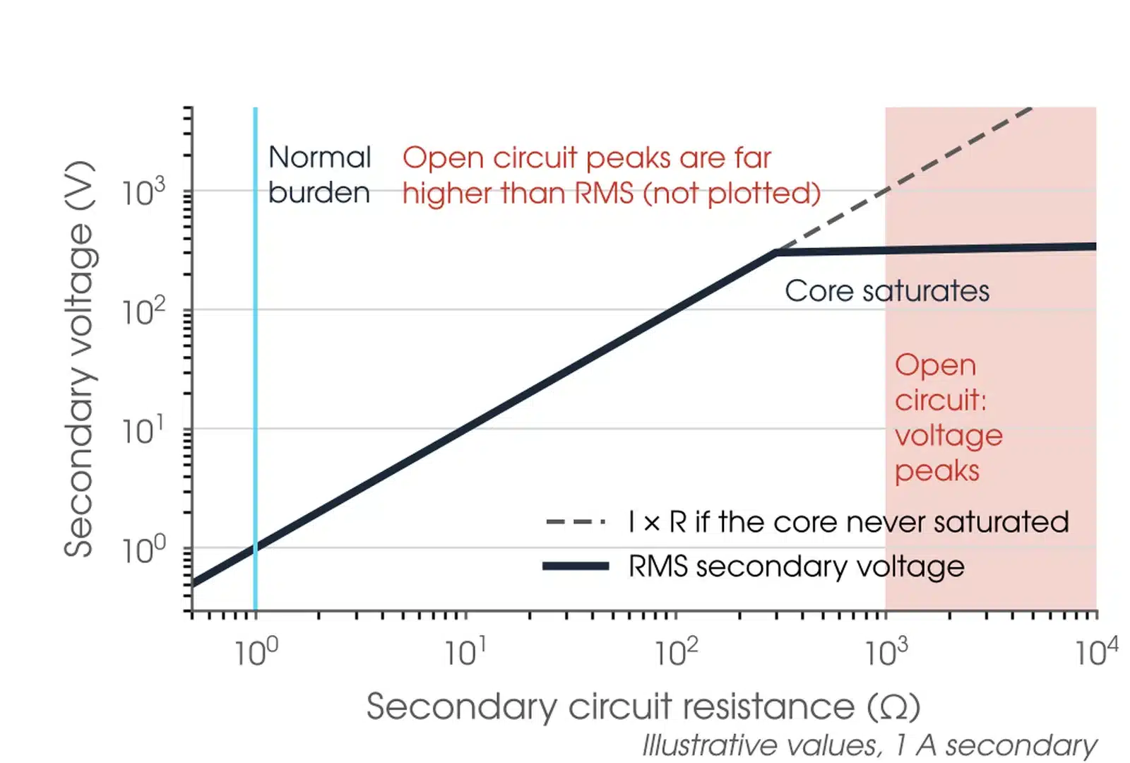
A CT is a current source: its secondary current is set by the primary current, not by the circuit it feeds. Open that circuit and the CT keeps forcing its current into the open point, so the secondary voltage rises until the core saturates, and the voltage then appears as high peaks. IEEE C57.13-2016 (clause 6.7.1) states CTs should never be operated with the secondary open, and asks users to consider a voltage limiting device where the open circuit voltage would exceed 3,500 V peak. A short gives the current a path, so the link can then be opened with next to no voltage across it. A CT wire in service reads about 0 V and still carries current, so a meter reading never makes a CT wire safe to remove: the short goes on first.
Why must a VT secondary never be shorted?
A VT is a voltage source. A short on its secondary draws a high current, can blow the VT fuses or damage the VT, and removes the voltage from every device on that supply. A VT circuit is isolated by opening its link or removing its fuse, never by shorting it. Opening it also stops injected test voltage reaching the VT through that circuit, where it would be stepped up onto the primary.
When is secondary isolation needed?
For secondary injection, primary injection, CT and VT testing, circuit breaker testing, scheme commissioning and decommissioning: wherever other circuits in the panel stay live.

Which circuits are isolated?
Every circuit that connects the scheme under test to plant or to other schemes. Each type has its own principle.
| Circuit | Principle | If it is wrong |
|---|---|---|
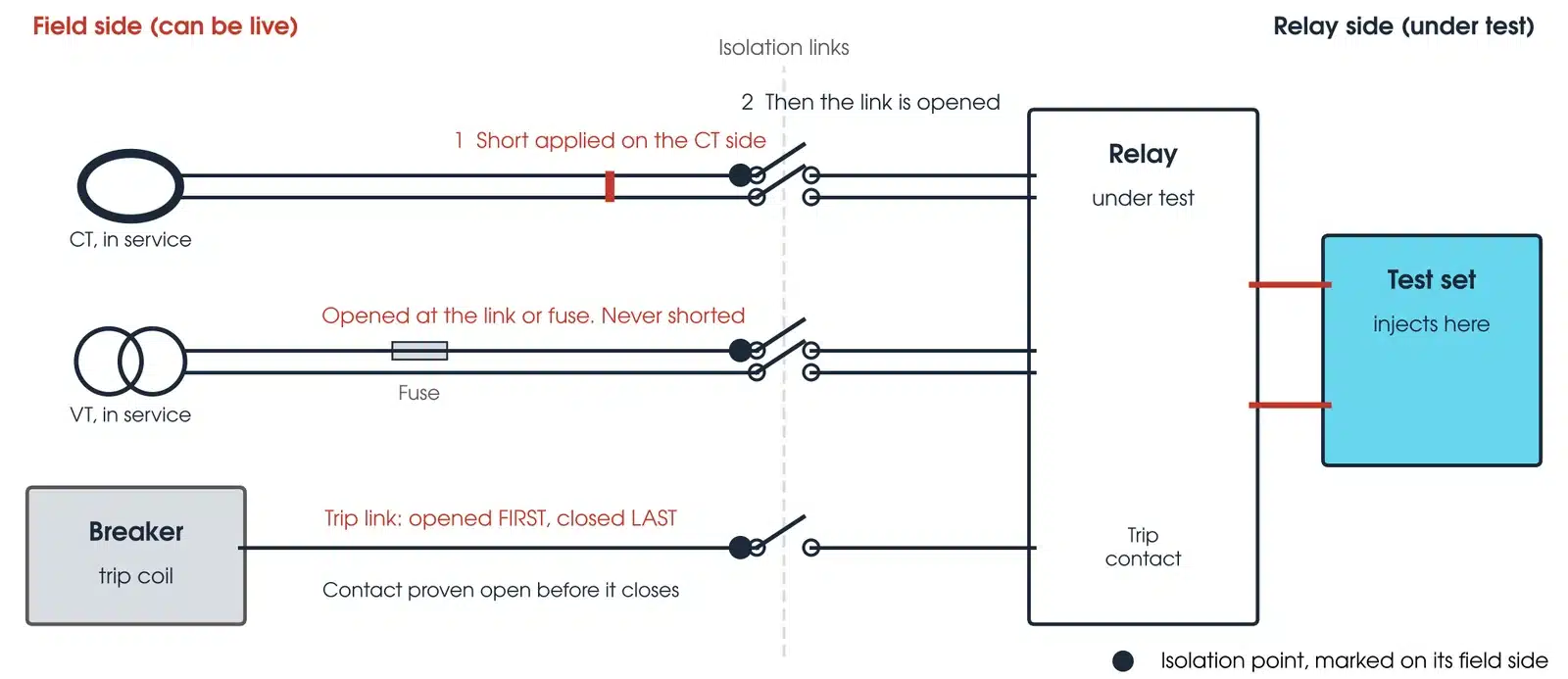
| CT secondary | Short the CT side first, then open the link; restore by closing the link, then removing the short | A dangerous voltage at the open point; CT damage |
| VT secondary | Open the link or fuse; never short it; never inject into it while connected to the VT | High current, blown VT fuses, voltage lost to every device on that supply; a back-energised VT primary |
| Trip and breaker fail | Open first, restore last; prove the contact open before the link is closed | A live breaker or adjacent bay trips |
| Intertrips and communications | Find out what the scheme does when communications are lost before isolating | The remote end trips, blocks or switches to backup |
| Software and IEC 61850 signals | A blocked trip or GOOSE signal is a trip isolation, made with the trips, once its effect on every subscriber is checked | A trip sent over the station bus while hardwired links are open |
| Alarms, SCADA and metering | Tell the control room; involve the metering provider for revenue metering | False alarms, or lost metering data |
The order matters. With trip, breaker fail and intertrip circuits open first, an operation of the scheme during the CT and VT work cannot reach plant through those circuits. Restoration is the reverse: CT and VT circuits are restored and the protection confirmed stable before any trip circuit is restored. One CT or VT often feeds several schemes, and other schemes on the same circuit stay in service and need the same care. Relay test mode alone is not an isolation: physical outputs and GOOSE paths are isolated to the approved plan.
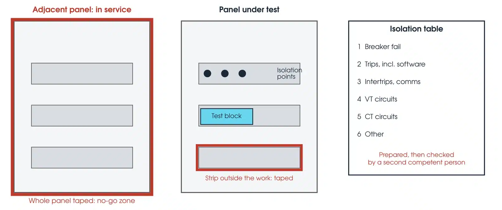
The rules that apply: the network operator's or site's safety rules and the access permit govern every isolation, and nothing in this guide relaxes them. IEEE C57.13.1-2017 Annex A covers test switches, test plugs and multiple earths in CT circuits. AS 2067 clause 2.1.1 requires testing and commissioning to be carried out by qualified and competent personnel. Our practice is a written isolation table, in the order the isolations will be made, checked by a second competent person before it is used.
How are secondary circuits isolated?
At four kinds of isolation point. Sliding or removable links in the panel terminal strips open one circuit at a time and are marked at the isolation point. A test block can open several circuits when its cover is removed or a plug is inserted, so what each does to every CT, VT and trip circuit is read from the drawings before it is touched. A shorting switch is make before break: it shorts the CT side, then opens the relay side, and IEEE C57.13.1 (Annex A.2.2) notes it does not earth the CT. And elements, outputs and IEC 61850 signals blocked in relay software are recorded and removed like any other isolation.
What is the purpose of a CT shorting block?
A CT shorting block lets a CT secondary be shorted on the CT side before the relay side is opened, so the CT is never open circuited while current flows. It turns the first rule of CT circuits into a piece of hardware: the short goes on, then the circuit to the relay is opened, and on restoration the circuit is closed before the short comes off.
How does shorting block work?
Shorting screws or links join the CT terminals together on the CT side; the links to the relay are then opened. On a test block the plug or the cover does the same job, and on some blocks the CT is shorted only by links fitted to the test plug, which is why the drawings and the block type are read first. Before a test plug goes in, IEEE C57.13.1 (Annex A.2.1) asks for a complete low impedance path through the ammeter to be confirmed.
How do I short out a CT?
Only under the site's rules and a checked isolation table. The principle: the CT circuit is given a sound short on the CT side before anything opens the circuit to the relay, and the short comes off only after that circuit is whole again. The isolation table, not memory, sets the order.
What are the steps of an isolation procedure?
The site's rules set the procedure. The principles behind every secondary isolation run in seven stages, and the order is the point.

- Prepare and check the table. Write the isolations from the current drawings, in the order they will be made, and have a second competent person check it before it is used.
- Delineate. Mark panels, cubicles and terminal strips outside the work as no-go zones, and mark each isolation point on its field side, the side that can be live.
- Isolate trips first. Breaker fail, trips and intertrips, including software trip signals, are opened before any VT or CT circuit.
- Short CTs, open VTs. Each CT is shorted on its own side before its link opens; each VT is opened, never shorted.
- Test. Within the isolated scheme only.
- Restore CTs and VTs and confirm stable. Nothing picked up, no trip output, no new alarm, and correct measured values where the plant is in service.
- Prove contacts, restore trips. Each trip contact is proven open before its link is closed.
Before the first isolation the access permit is held and the control room told which protection will be out of service and for how long; any outage of protection on in-service plant is agreed with the operator first. The panels are walked with the table, and existing isolations, unusual conditions and active alarms and LEDs are recorded before anything is touched.
This guide sets out principles for competent protection testing personnel. It is not a work procedure and does not replace one. The network operator's or site's access and safety rules, the access permit and a site-specific safe work method statement govern every secondary isolation, and take precedence over anything in this guide.
What are the common secondary isolation mistakes?
| Mistake | What it causes |
|---|---|
| Isolating from memory | No table, or a table nobody checked |
| CT link opened before the short | A dangerous voltage at the open point |
| Trip restored before the CTs | The scheme operates on restoration and trips plant |
| Test mode taken as isolation | A GOOSE trip reaches the breaker |
| Test block not understood | The cover or plug opens, or fails to short, a circuit nobody expected |
| Short removed with the plug in | The CT opens through the test plug |
| Markers and existing isolations missed | A marker left in, or an existing isolation lost at restoration |
How do I check a restoration?
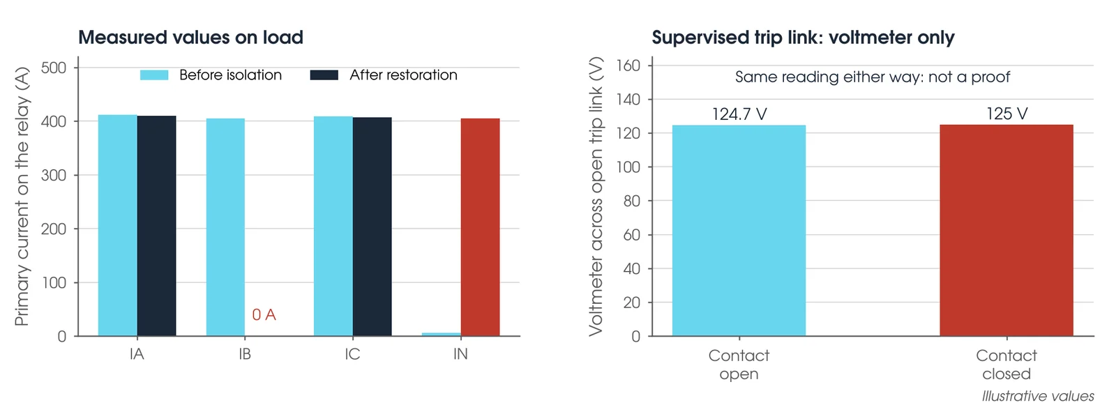
Against the record made before the work. Alarms, flags and LEDs should match what was recorded before the first isolation. With plant in service, each phase current and voltage on the relay should be consistent with the other phases and the system load. Every isolation made for the work should be restored and initialled, every software isolation removed, every CT short counted back and every temporary marker removed.
| What you see | What it usually means |
|---|---|
| One phase current at zero | A CT short left on. If an open CT link with no short could be the cause, treat it as an open-circuited CT: a dangerous voltage is present. Stop and keep clear |
| Neutral current on balanced load | A phase missing or reversed in the CT circuit |
| Voltage missing on the relay | A VT link or fuse not restored |
| A new alarm | Something not restored, or restored in the wrong order |
| Protection picked up | Stop: leave the trips isolated and find the cause before going further |
Is the restoration complete?
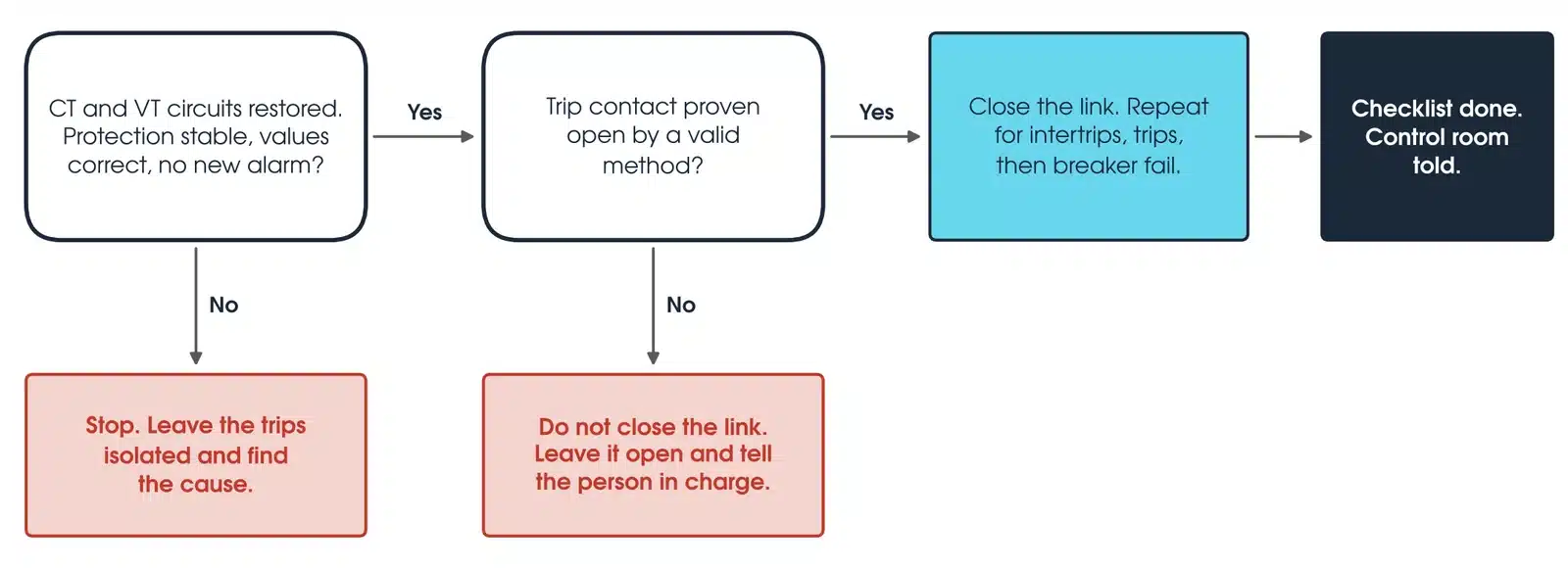
Only when the protection has been confirmed stable after the CT and VT circuits are restored, every trip contact has been proven open before its link was closed, the checklist is complete and the control room has been told the protection is back in service. If the protection is not stable, stop, leave the trips isolated and find the cause. If a trip contact cannot be proven open, the link stays open and the site leader is told.
Why can a voltmeter not prove a supervised trip contact open?
In a common trip circuit supervision arrangement, a high resistance sits across the trip contact, so across an open trip link the meter and the supervision input form a divider: V(meter) = Vs × R(meter) / (R(meter) + R(supervision)), where Vs is the station battery voltage. Worked example, illustrative values: a 125 V battery, a supervision input of 25 kΩ and a meter of about 10 MΩ give 125 × 10,000 / 10,025, about 125 V, with the contact open. With the contact closed and the trip coil connected it also reads about 125 V. The meter cannot tell them apart, so a different proving method is needed.
What should be recorded?
Every isolation, its point and wire, initialled as it is made and as it is restored. The isolations and alarms found before the work, confirmed still in place afterwards. The times, the operator's name and any protection outage agreed. And the restoration checklist, the CT short count and the time the control room was told the protection is back in service.
What about high impedance schemes and test blocks?
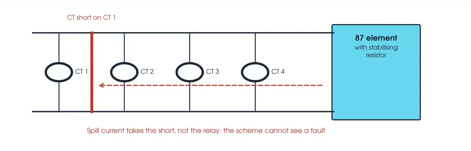
A high impedance scheme operates on the voltage that spill current develops across the relay. A CT short connected to the scheme's common wiring gives that current a low impedance path around the relay, so a real fault is not seen. The scheme is disabled from the moment the short goes on until its link is open, and again on restoration, so the operator agrees that outage first and it is kept as short as possible. Taking one CT out of a scheme whose primary is in service unbalances it, and it can operate on load; its trips are isolated first.
At a test block, confirm from the drawings, the block type and the plug type what removing the cover and inserting the plug do to each circuit. If it cannot be confirmed, the cover stays on. A trip circuit that the plug opens is also opened at its own link, so it stays open when the plug comes out and is restored last.
Which test sets are used once a scheme is isolated?
The isolation makes the test possible; the test set does the test. Every instrument below is available calibrated, with leads, from Megavar.
| Instrument | Capability | Best used for |
|---|---|---|
| OMICRON CMC 356 | Six current and four voltage outputs | Secondary injection once the scheme is isolated |
| OMICRON CMC 500 with IEDScout | Multiphase test set with IEDScout | IEC 61850 schemes, including GOOSE isolation checks |
| OMICRON CPC 100 | Primary injection to 800 A | Proving CT circuits through the real wiring, with the primary dead |
| Megger SVERKER 760 | Single phase, up to 100 A or 250 V | Single element relay tests |
Every instrument is available from Hobart, Launceston, Adelaide and Newcastle through Megavar's primary injection hire and relay testing equipment hire. If you would rather have the scheme tested, Megavar's engineers carry out protection relay testing and substation commissioning across Australia. The tests that follow an isolation are covered in the protection relay testing guide, the CT testing guide and the VT testing guide.
Download the secondary isolation guide (PDF)
Frequently Asked Questions
What is the purpose of a CT shorting block?
It lets a CT secondary be shorted on the CT side before the relay side is opened, so the CT is never open circuited while current flows.
How does shorting block work?
Shorting screws or links join the CT terminals together on the CT side; the links to the relay are then opened. The order is short first, open second.
How do I short out a CT?
Only under the site's rules and a checked isolation table. The principle: the CT circuit is given a sound short on the CT side before anything opens the circuit to the relay, and the short comes off only after that circuit is whole again.
What are the steps of an isolation procedure?
In principle: a checked table, delineation, trips first, CTs shorted and VTs opened, the work, CT and VT circuits restored and proven stable, trip contacts proven open, trips restored last. The site's rules set the procedure.
Why is a CT shorted before it is opened?
The CT keeps driving its current. With nowhere to go, it develops a dangerous voltage at the open point (IEEE C57.13-2016, clause 6.7.1).
Why must a VT secondary never be shorted?
A VT is a voltage source: a short draws a high current, blows its fuses or damages it, and removes voltage from every device it supplies.
Who should make secondary isolations?
Competent protection testing personnel (AS 2067, clause 2.1.1), authorised under the network operator's or site's access rules.
Does Megavar test protection schemes?
Yes, including IEC 61850 GOOSE schemes. Call 1300 730 499.
Need a protection scheme tested?
Megavar tests and commissions protection schemes across Australia, from 11 kV distribution to 500 kV transmission, and hires the relay and primary injection test sets in this guide. Call 1300 730 499 or email service@megavar.com.au.